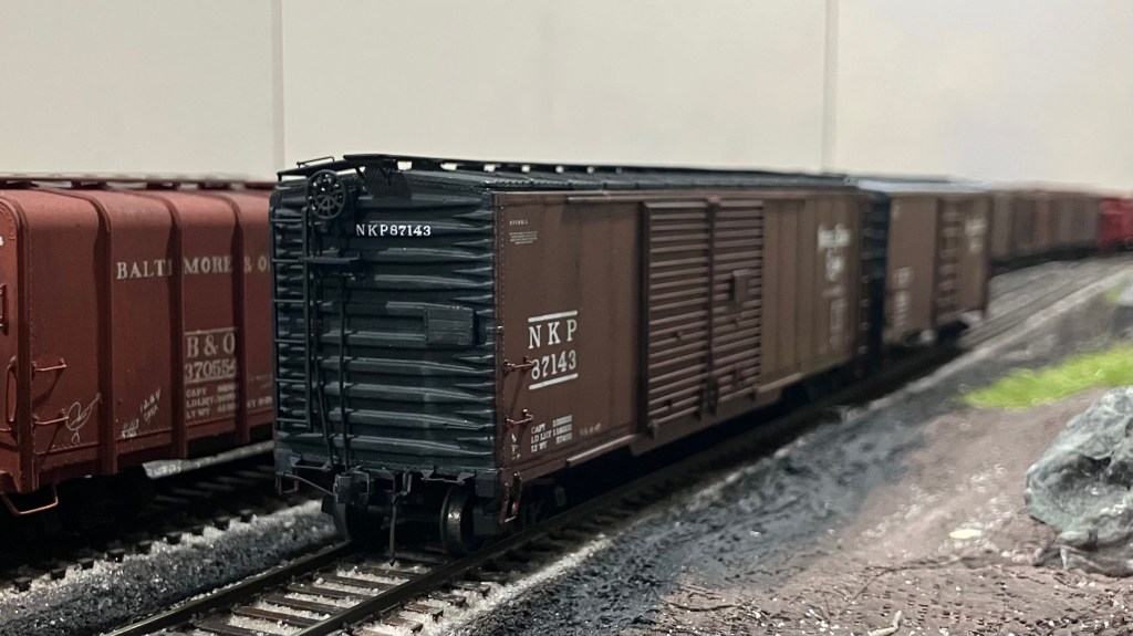
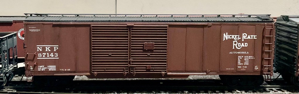
A few weeks ago I found a Life-Like Proto 2000 (P2K) 50′ doubledoor boxcar in my collection of unbuilt kits. I assumed it was probably close to accurate to the prototype car, otherwise I probably would not have bought it, or maybe it was destined for a kitbash into something totally different. I honestly could not remember, I think it has been in my possession since sometime in the early 2000s. The $7.00 price sticker is still in place on the end of the box.
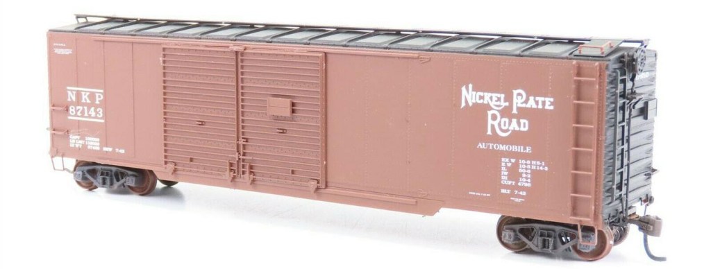
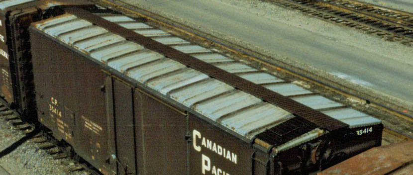
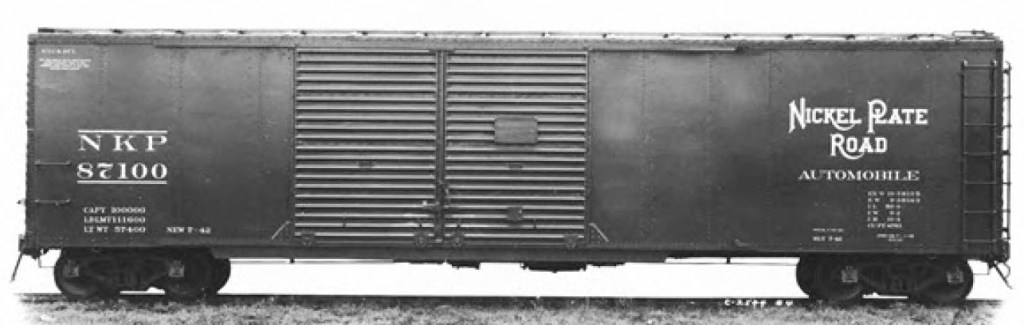
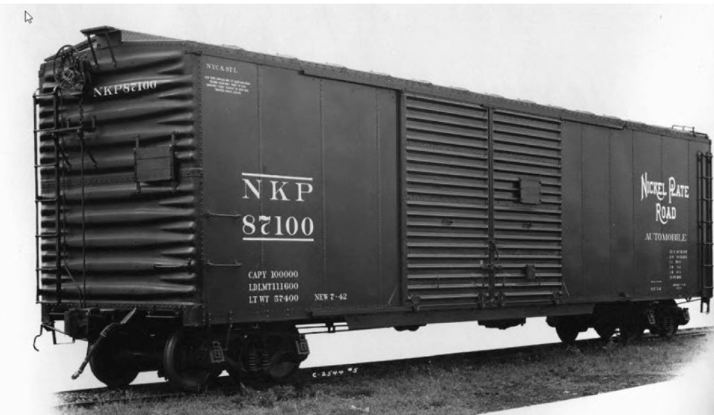
To get more information I did a search on the Steam Era Freight Car .IO group (main@RealSTMFC.groups.io) for “NKP 87143”. It was a lucky guess for a search term and I immediately found information from conversations back in the 2000’s. They generally indicated the model was a faithful representation of the prototype, except that the model was not equipped with a Viking Roof and a Apex Tri-Lock metal running board of the prototype.
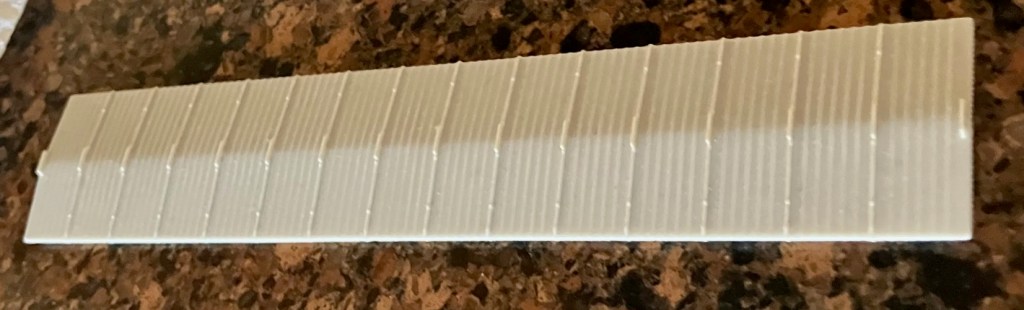
I found a 50′ injection molded Viking roof on eBay for $17 delivered. So this build jumped the line, while other builds sit half finished. I had a black 50′ Kadee Apex Tri-Lock running board on hand, so with the basic parts needed it is time to start and finish a simple kitbash.
The first step in the kitbash is to remove the roof from the P2K model. I lightly scribed the sides of the roof just above where they it meets the car side and cut the end of the roof across the top about 1/16” from the edge with a very fine razor saw. I bought mine from UMM several years and it is irreplaceable for this type of fine cutting (https://umm-usa.com/onlinestore/tools-supplies-cutting-jlc004-years-anniversary-micro-pack-p-37.html). I filed and sanded the cut surfaces to achieve a tight fit. I brush painted the cut and sanded surfaces with Vallejo Model Air Black 71.057.
I washed the new roof with dish detergent and after it was dry I gave it a very light coat of Tamiya 87064 Fine Surface Primer – Light Grey. After drying for a few days, I airbrushed the roof with the same Model Air Black and then a matte finish.
To install the Kadee 50’ running board I used four of the mounting pins molded on the underside. The second ones from each end fell right next to roof supports so I didn’t have to drill through the thin supports. I also kept the one under each lateral portion of the running board. I used canopy glue on the underside of the roof to attach the mounting pins and on the support brackets on the roof where it wasn’t laying flat. The finish on the Kadee part is glossy, so I sprayed it with Windsor & Newton Matt Varnish. After dry, I glued the roof to the carbody.
I chose to use Kadee #178 Scale Whisker Couplers with Scale Draft Gear instead of the provided P2K parts. The stock draft gear boxes are not designed to be screwed in place, just cemented. I prefer a mechanical connection in addition to adhesive. There are two holes in the floor and the one closest to the end I threaded with a #80 tap and used the screws provided with the couplers. I filled the gap between the coupler pocket and the frame with a piece of styrene.
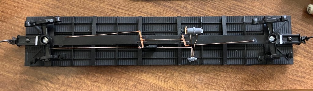
For a more detailed underbody, I substituted parts of the Tichy AB #3013 Brake Set, Tichy phosphor bronze wire, and Yarmouth Model Works YMW-503 Brake Levers for the supplied parts and airbrushed them with Model Air Black. I put the air reservoir pipes in the wrong location after making the mistake of looking at the diagram upside down. I’ll live with it.
The side sill reinforcement on the prototype is not as long as the one on the model. I used a razor saw to trim the right end of the sill to match the prototype photos.
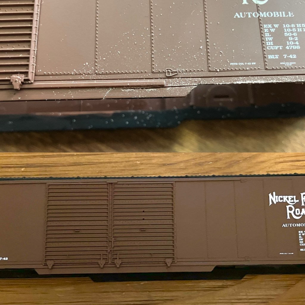
The prototypes placard boards were made from three boards placed horizontally and the supplied parts were not a good match. I used National Scale Car (NSC) P-1 resin placards. To match prototype photos, the end placards were mounted lower than indicated in the kit instructions and the extra hole filled with Vallejo Acrylic Putty. The model was not supplied with route card holders, so the I used the ones on the NSC P-1 parts sheet mounting them low on each side’s right hand door.
I am not sure how close Life-Like was to matching the NKP paint color, but Vallejo Model Color 70.859 Black Red is a very close match to the paint on the decorated model. I used it to paint the placard boards, route card holders, and sill steps.
The sill steps, YMW #207, are attached with ACC to a .010” wire glued into the factory mounting hole with the etched part fitted onto the wire. The wire simulates a rivet securing the sill step to the sill. Not a perfect scale representation, but they are sturdy.
The model’s bottom end grabs were replaced with Kadee 2252 end grab irons, and rest of the stock B-end details were installed. Removing the poling pockets to match the prototype was relatively easy and the bare plastic was touched up with Vallejo Model Color Black (Model Color is designed for brush painting).
Kadee #2250 bracket grab irons were installed with the help of a Yarmouth YMW-502 template to locate new holes. They were brush painted with Vallejo Black Red. The ladders were not an exact match for the prototype’s but after replacing the roof I didn’t want to also build new ladders for what I feel are relatively small discrepancies. The stock ladders look good.
Before gluing the body to the underframe I added an additional one ounce of weight to the supplied steel weight. For my 1950 layout date, I added new reweigh and repack decals and few chalk mark decals. I also used a Sakura Gelly Roll .5 mm white pen for chalk marks. It worked pretty well, it was part of a three pen set I found on AMazon for less than $6. Blick Art Materials carries this brand also.
After the body and underframe are glued together, High Tech Details #6039 22″ A.A.R. Air Hoses w/Brackets and Tangent Coupler Lift Bars with Mounting Brackets (SKU 210) were added to each end and painted Vallejo Model Color Black.
While I was working on these upgrades to the stock kit, a prolific prototype modeler contacted me for information about this build. He didn’t need to know how to add brake details, just the big picture changes, so I added the checklist below for folks who just want the basics of my changes.
*Change roof to 50’ Viking roof
*50’ Kadee Apex Tri-Lock running board
*Kadee #158 couplers and Kadee “scale” draft gear
*NSC PS-1 door route boards and three-panel placard boards
*Tichy and Yarmouth AB brake parts
*Reinforcement plates at lower door corners – colored decals
*One ounce of weight to meet NMRA guidance
*Trim side sill reinforcement on right side of doors
*Metal sill steps, YMW #207
*Remove poling pockets
*Side grabs Kadee #2250 bracket grab irons and Kadee 2252 end grab irons
*Tangent Coupler Lift Bars with Mounting Brackets (SKU 210)
*Brake hose with bracket, High Tech Details #6039 22″ A.A.R. Air Hoses w/Brackets
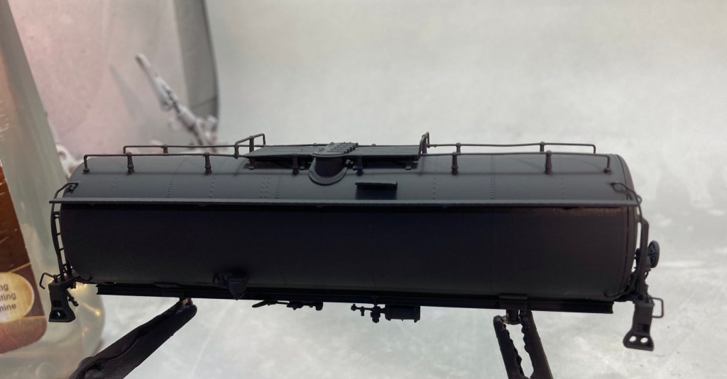
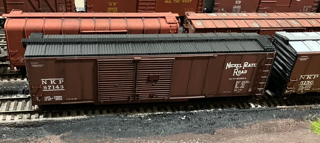
My preferred matte finish, Windsor & Newton Matt Varnish with a few drops of light grey, was airbrushed over the finished car along with black panel line wash on the rivet lines, and grey on the roof and ends. An application of dark weathering powders completed the model.
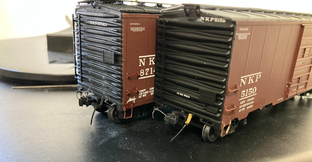
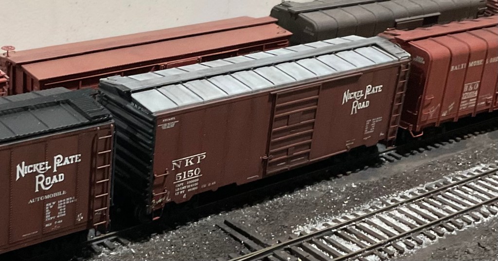
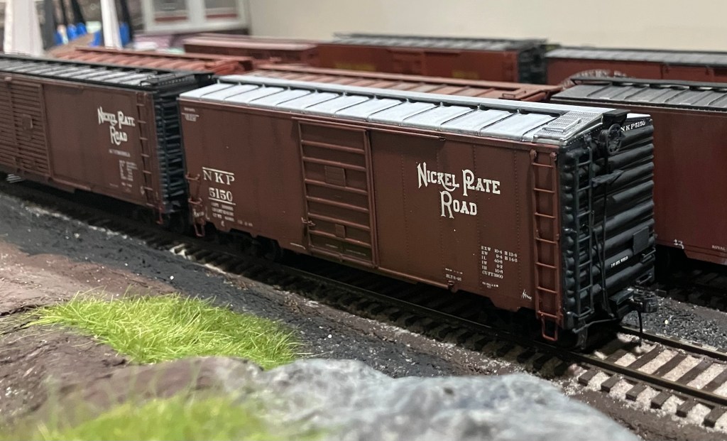
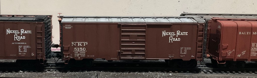
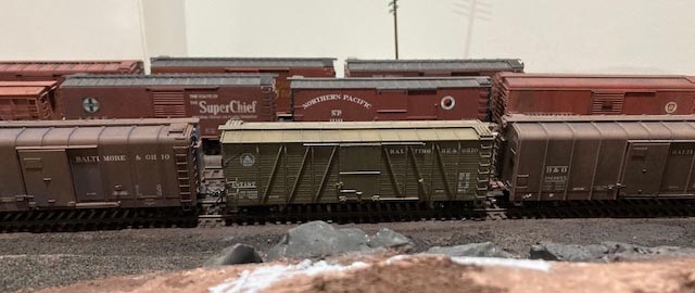
While I was modifying this kit, I found a ready to run NKP boxcar on the shelf that could use some of the same TLC. It is an Atlas ready to run 40′ Postwar Boxcar w/7′ Door Road #5150 (Part # 150-20004251) with a broken coupler mount box and shiny silver roof. Instead of replacing the roof, I had to tone it down with some light oversprays of Vallejo Model Air 71.005 Grey Blue and 71.050 Light Grey, followed by the seam caps painted black with a Faber-Castell Pitt Artist Pen (it is good for reefer hardware also). This car got slightly less weathering because the paint job is about five years newer in my era. Now I have some roof variety and NKP boxcars on the layout.