While Ilchester was a small station for an even smaller town, it did have a long history and still had railroad deliveries into the 1950s. Across the Patapsco river on the north side was the Thistle Manufacturing Company. In 1823, four years before the B&O was chartered the land for the factory was purchased from the Ellicott family (the family that settled Ellicott Mills, later called Ellicott City and the first terminus of the B&0). The Thistle Manufacturing Company was chartered in 1834 and was thought to be designed to supply cotton duck to the shipping industry in Baltimore. According to records, it manufactured cloth through the 1800’s.
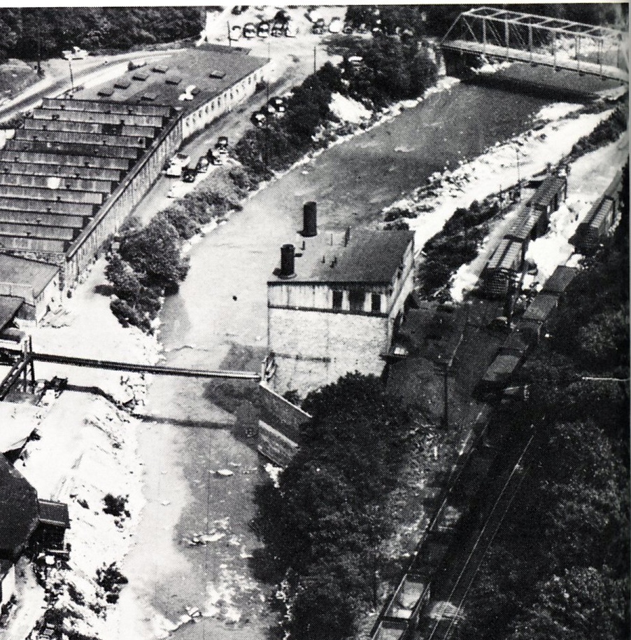
In the early 1920s it began to manufacture automobile tire bands, but by the late 20s was producing cardboard boxes. In 1928 it was sold to Bartgis Brothers and they manufactured boxes until 1957 when it was sold again. Box manufacturing and then paper recycling continued on the site for many years, but it has since been leveled. From a 1940s era aerial photo it appears paper pulp was delivered to the plant in boxcars on the south side of the river. The pulp is the light fluffy substance and appears to be on the ground near boxcars on the north siding track in the aerial photos. It seems to have been shipped in bales like cotton in that era. This intermediate product was likely unloaded from boxcars and trucked north cross the river to the Bartgis Brothers Plant. Swedish paper pulp was an import to Locust Point and may have been a source for Bartis Brothers. A January, 1950 article in the B&O magazine shows imported pulp from Sweden being handled at Locust Point.
It is interesting to note that the plant was connected to the sewer system in 1970 and no longer allowed to dump titanium dioxide directly into the river. This white substance seems to be visible in the aerial photos, now I have to decide whether or not to model the river as polluted or not.
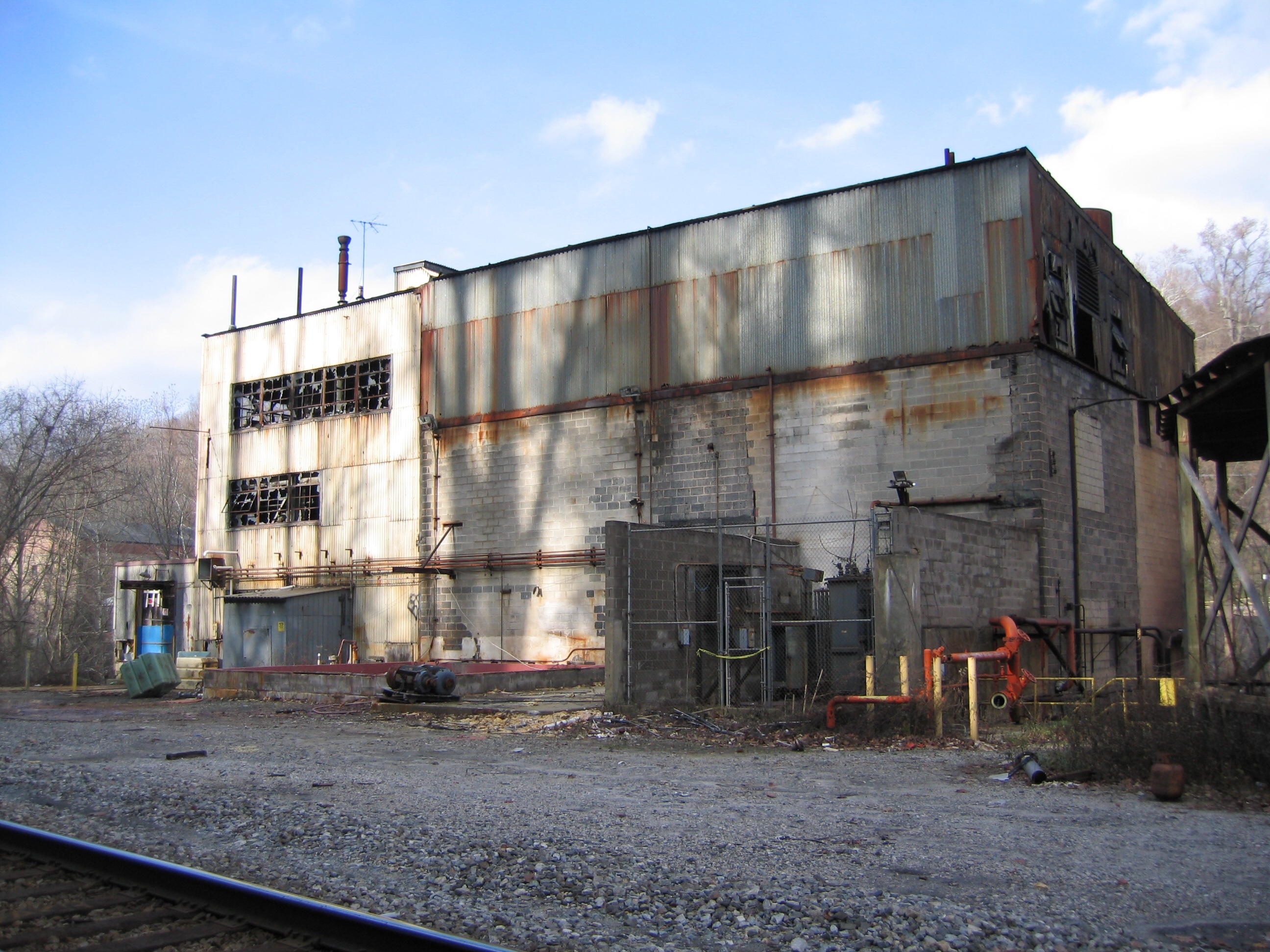
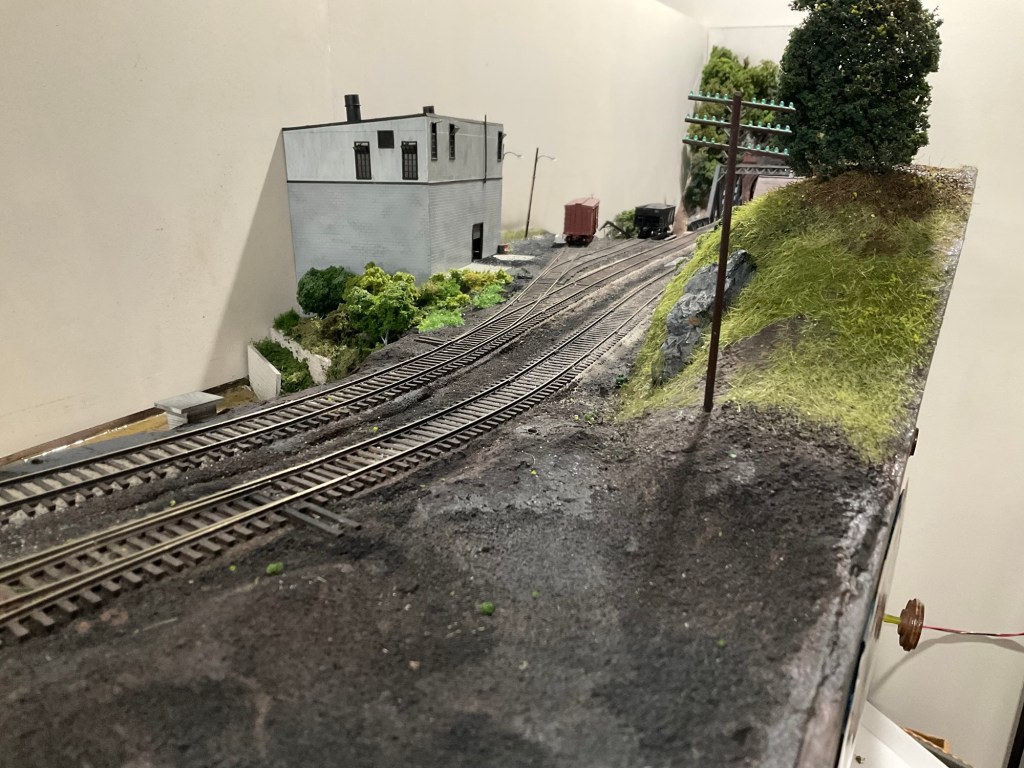
A new power plant for the newly named Bartgis Brothers Plant was built across the river (on the same side as the railroad) sometime between 1920 and 1940. It was initially coal fired and at some point between 1940 and 1960 three tall coal storage silos were added on the south side, closest to the rail siding. Before the coal silos, it appears the company used the existing company coal trestle along the north side of the right of way and brought coal up the small hill and dumped it on the ground near the building to feed the boilers. Since I can’t nail down a date for the addition of the storage silos and they seem to appear around 1952, I am going to stick with the trestle as the coal delivery method.
Two photos over the course of twenty years show the change, but their dates are too far apart to be exact. One seems to show a truck delivering coal and the trestle seems like a likely source. It seems very labor intensive, but in this time period labor was cheap compared to building more automated delivery systems and this appears to be a temporary solution until the silos were built. Remnants of the trestle exist today and early photos show it in the 1920s. Its construction was covered in an earlier blog.
According to the B&O Officers’ Special Train report published in 1953 Bartgis Brothers received 43 carloads in and 0 carloads out in September 1953. The inbound cars were likely coal for the power plant and pulp for the primary operation. Other reports from the early 1940s indicate they shipped cardboard products to North Carolina and other states supporting the war effort. A B&O memo dated 1944 indicates that the in 1943 the plant received 459 cars of coal and shipped 125 carloads of box board. I assume that as interstate trucking began to develop it took more and more of the outbound freight. Photographs from the late 1960s still show boxcars on the siding, so they may have continued receiving pulp and/or shipped product out be rail.
The rail siding near the steam plant was also used for pulp deliveries at this time. The plant was manufacturing boxes, so pulp was the needed commodity. I am not sure of the source, but this January 1950 Baltimore and Ohio Magazine may show one source from Locust Point. A photo shows bales of Swedish pulp being moved by new equipment designed for the task. The aerial photos show what I believe to be a white fluffy substance near the boxcars which could be broken bales of paper pulp. I can’t be sure without company shipping records, but it is a plausible source, maybe not the only one for the Bartgis Plant’s raw material. I suspect finished product was shipped to local manufacturers, but again, this is supposition.
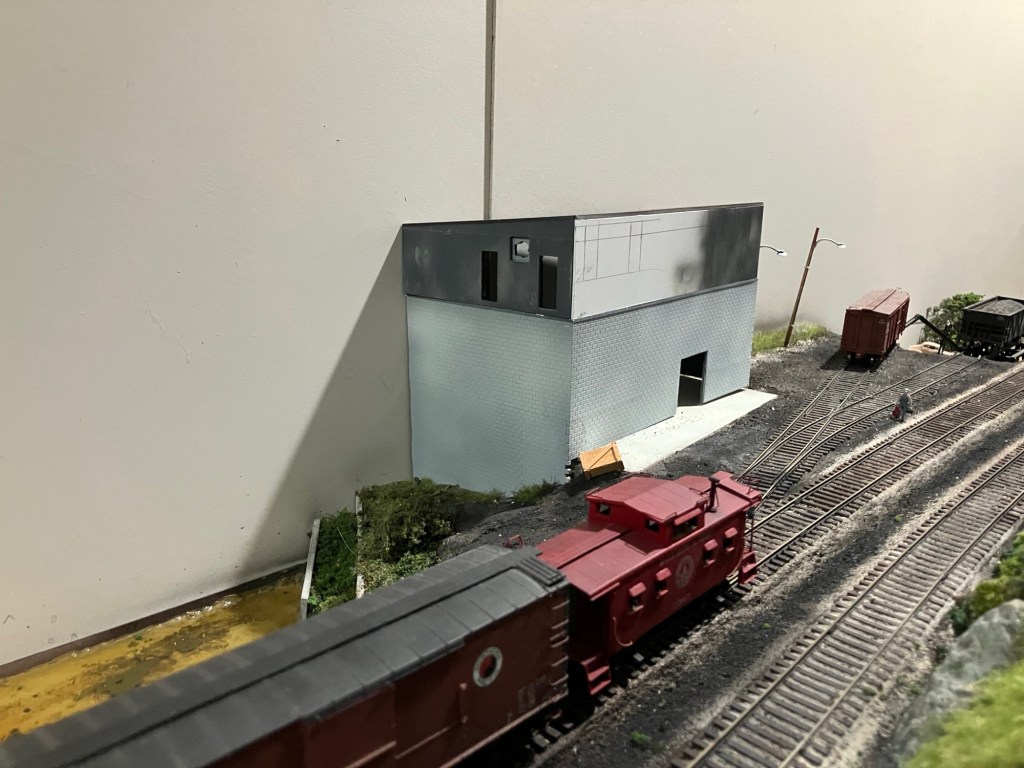
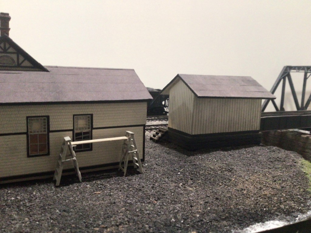
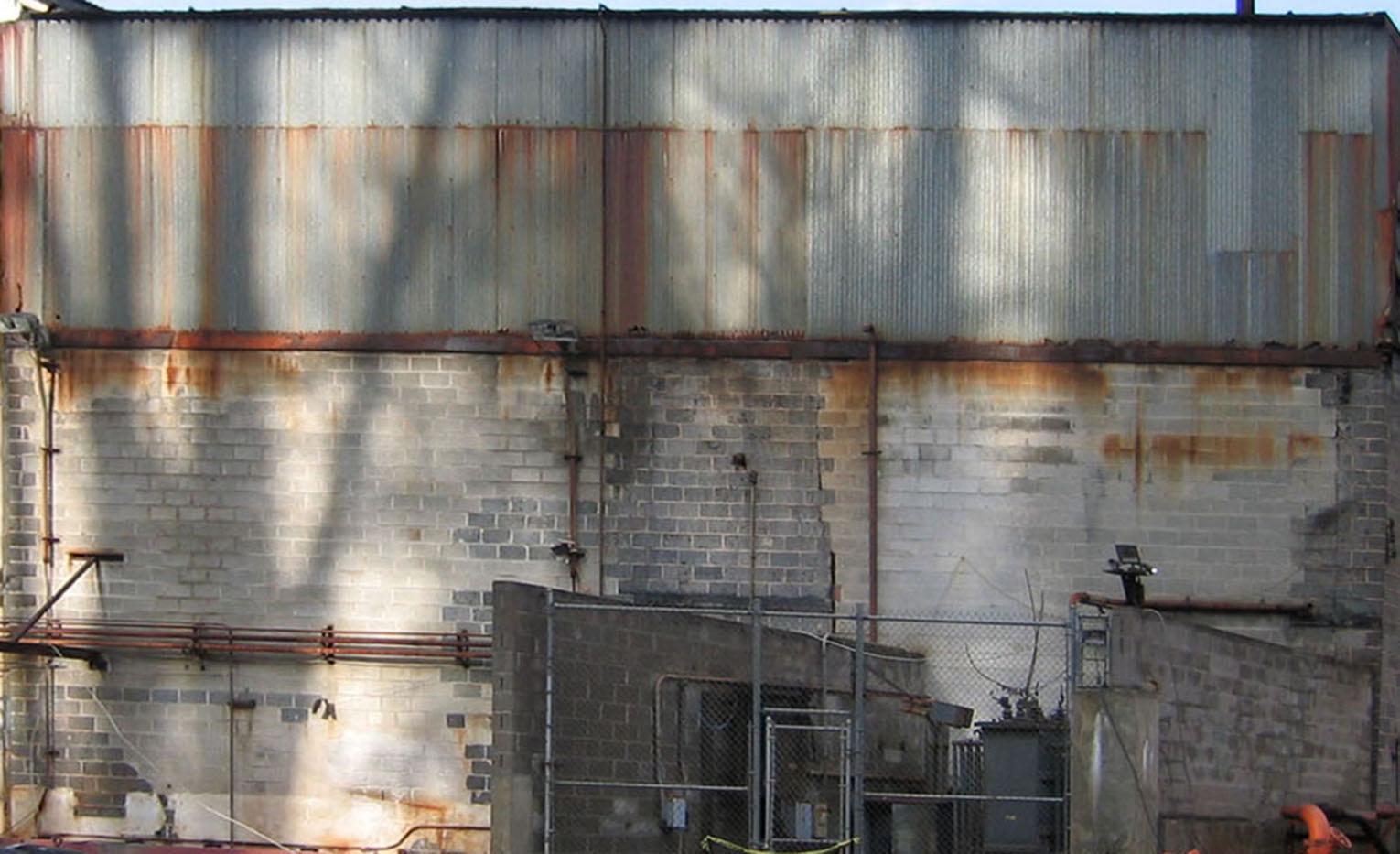
My model of the power plant started with the modern photo by John Teichmoeller, as the building was gone on my most recent visit in 2018. John’s 2006 photo appears to have an addition on the left that did not appear in period aerial views. Using PhotoShop, I squared John’s photo of the building and cropped it make the first mock-up (photos below). Using the standard 8″x 16″ cinder block size, I was able to get a close approximation of its size. The side of the building facing the track is about 62 ‘x 36’ high.
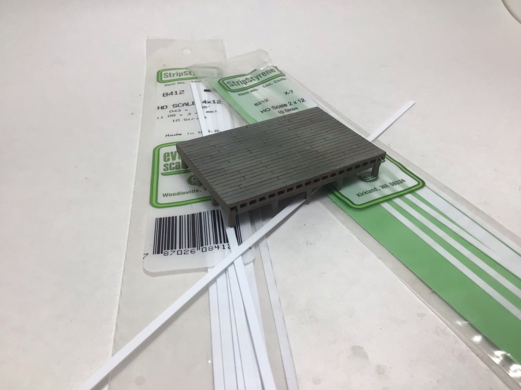
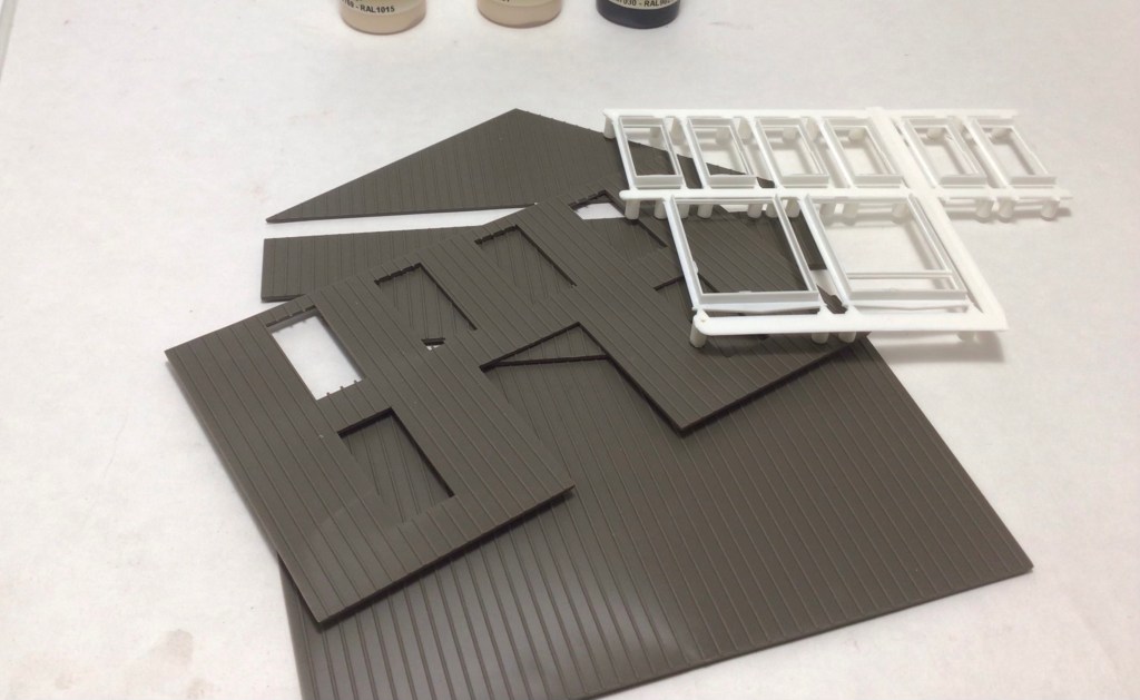
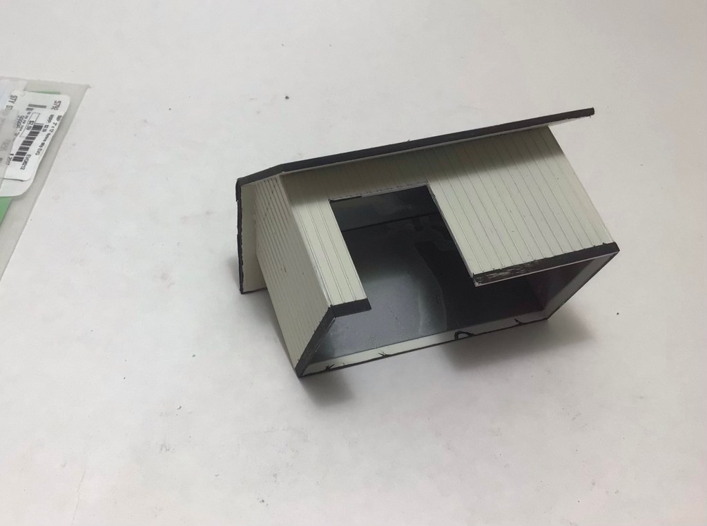
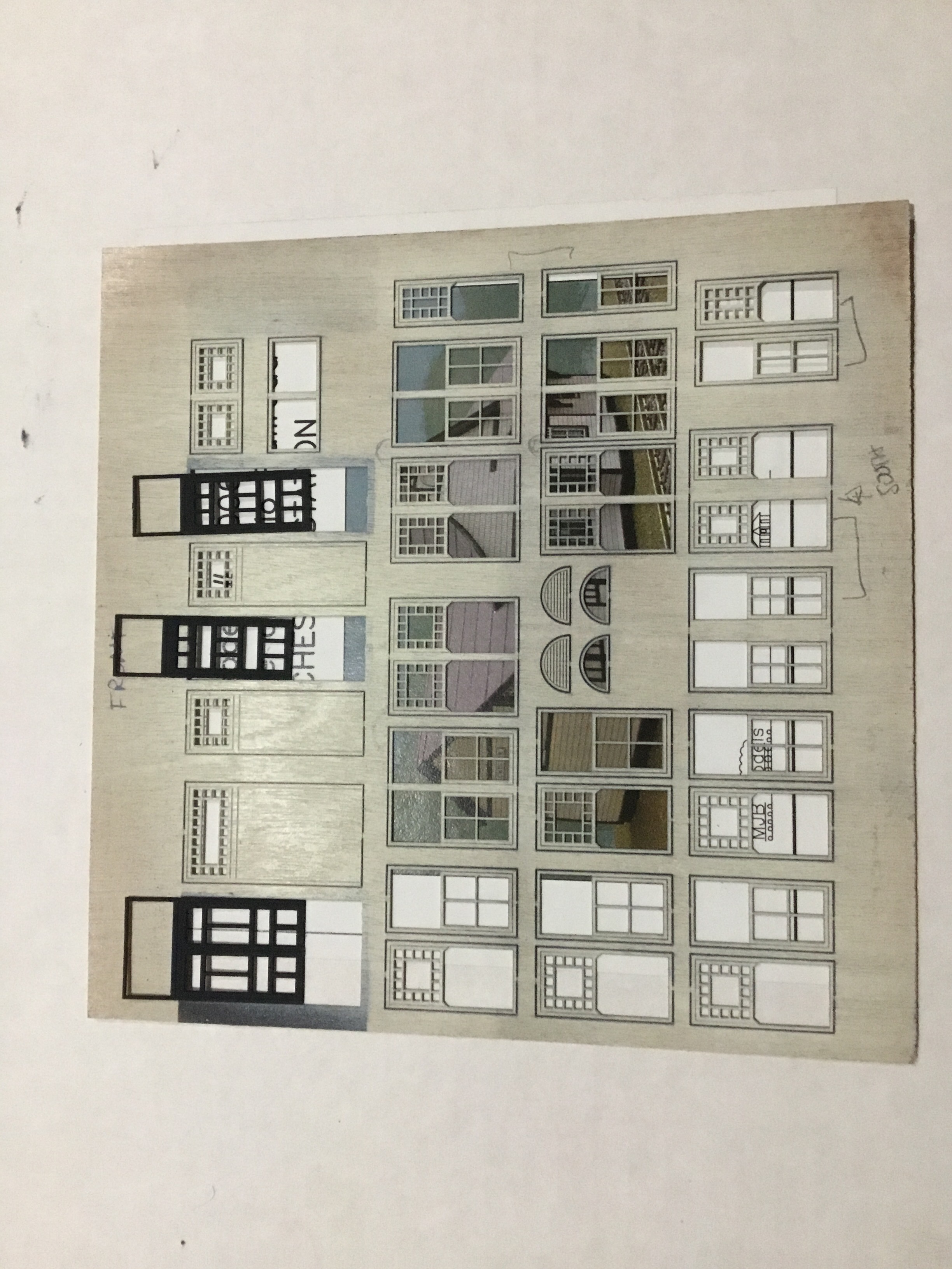
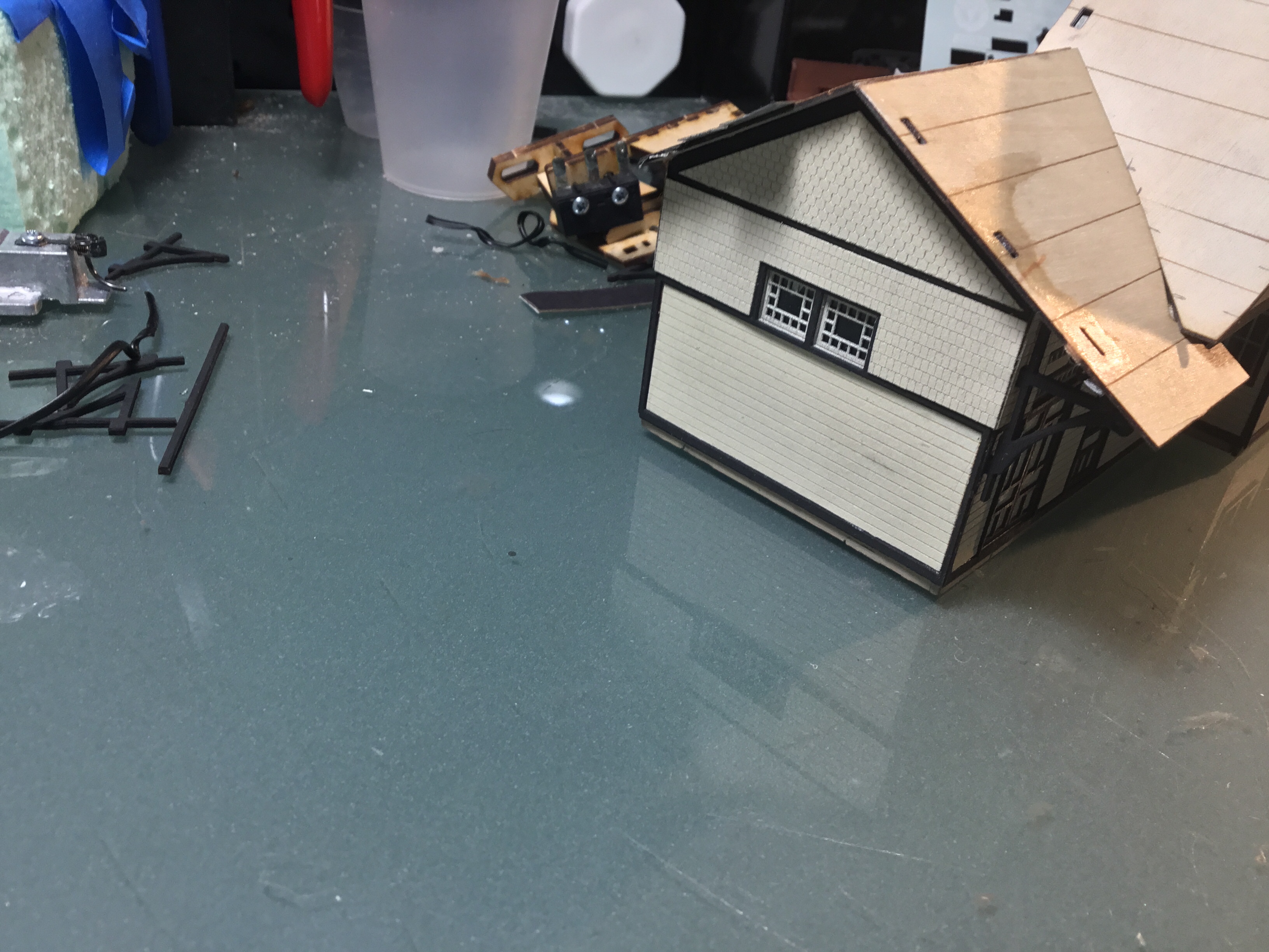
To replicate the cinder block walls I used Rix Products excellent Pikestuff Concrete Block Walls. I purchased several packs of Long, Intermediate, and Short Sections for less than $4.00 each. The products fit together perfectly and reading the instructions provided a key insight to keeping the joints tight. There is an “X” cast on the back of each section and these should always have the same orientation when joining sections. It is a small detail but it makes the sections fit seamlessly and hide the joints. The height of the wall sections was not tall enough to let me use a single section, so I cut sections along a mortar line and put the cut along the bottom of the wall. Keeping the “X” on the casting to the same side was again a key to smooth joints. The mock-up photo below shows that part of the process. In the in progress photo below, the top group of sections are glued together, the short height bottom one is not. The roll up doors are from the same product line and are scale 10’x 10′ (Pikestuff PKS-1109 Roll-Up Loading Doors). I wanted to use two, but it looks like the prototype only had one.

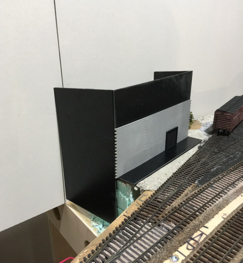
Using the squared, cropped photo as a guide, I cut the backing for the south facing (closest to siding and mainline) from .080 thick black Evergreen Sheet Styrene (product #9117). This piece was slightly undersized to final dimensions to allow the overlay of the Pikestuff Concrete Block Walls. Since my overall dimensions were estimates, I made the interior support walls to fit the interlocking block pieces for neat joints at the corners. While I was doing this basic framework, I used Evergreen #4037 to simulate the corrugated metal siding on the top half of the structure. For the openings in the structure, I purchased Tichy #8157 18 Pane Top Tilt Out Industrial Windows and PikeStuff 1009 Louvered Ventilators.
The lack of photo documentation gives my some latitude but I am looking for a measure of prototype fidelity, I have put this much time into it already, why stop now.
For the windows I wanted to recreate a hot August day in 1950, so they are open as seen in the aerial photo. The Tichy windows have a top frame that is adjustable so I chose to have it tilt out with a control rod to replicate the industrial windows that tilted out to relief the heat stress from the boiler and the summer temperatures.


The left or west side of the building extends down to the river near two large concrete block retaining walls built to protect it from flood waters. The steam and condensate return lines appear to exit the power plant near its north side below railroad grade. This is would be beyond the backdrop.

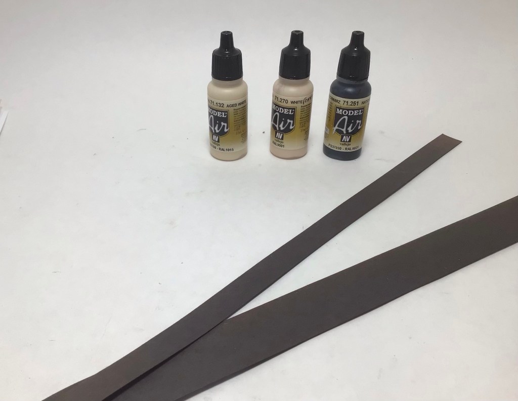
The roof appears to be pretty standard for the day and appears from aerial photos to the rolled tar paper roofing that I simulated with black construction paper cut into strips and adhered with contact adhesive. I used a black paint pen to simulate the tarred seems.
The aerial photo shows the siding that serves the power plant splitting right after leaving the main. The south line (closest to the main) serves the coal dump and looks to serve the main plant also with boxcars spotted railroad west of the coal dump. That north siding also seems to serve the main plant with just boxcars loaded with processed pulp. Trucks must have been used to move material across the river. The siding was pretty short and I modeled it that way so that two boxcars spotted for unloading foul the switch to the coal dump, requiring at least one to be moved to service the dump. A few extra moves for the Peddler crew to make because of the unplanned use of the coal trestle.