
With this post I am going to try something new. Sharing a blog post about an incomplete individual model. It’s something I don’t usually do because I was used to writing and editing for the B&O Modeler. Most articles were stand alone and if we ran a two part, it was usually because of space limitations, not that the model wasn’t finished. I like the style of successful and very informative modeling blogs like Rick De Candido’s and Eric Hansmann’s, as they share smaller bite sized posts. They keep my interest in modeling high, especially during the summer with so many more leisure activities available.
One of my first sound equipped HO locomotives in the early 2000’s was a Broadway Limited Imports (BLI) USRA Light Mikado. It would run under the Christmas tree on my small, circular HO layout for hours under DC power. I later added a BLI “black box” that connected to the layout wiring to let me control the basic sounds. I was hooked on sound and knew DCC with sound, though expensive at the time, was in my future.
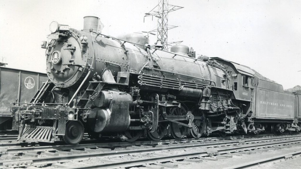
The B&O had the first USRA Light Mikado, #4500, and it still exists at the B&O Railroad Museum in Baltimore. It was unique from later builds in a few ways including the cab shape and cab size. The BLI model is a more generic USRA “common build” model. The B&O changed many things on their USRA Light Mikados (Mikes in B&O parlance) over the years and classed these locomotives, Class Q-3. The most visible changes to their USRA Mikes included; adding an extended cab on the fireman’s side to accommodate a seat for the headend brakeman (this was done on many B&O Mikes), a twelve bolt smokebox front, a high mounted headlight, number plate or B&O Capitol Dome in the smokebox center, and the bell moved from the smokebox to behind the sand dome. There are more and I will add them to the conversation as I add detail parts to the model.
All B&O Mikados or Mikes were in the Q-series of locomotives. A great source of information on this B&O series of locomotives is Q The Definitive History of the Baltimore and Ohio Railroad Company’s Q-Class Mikado Locomotives by by Howard N. Barr (Author), William A. Barringer (Author), Harry C. Eck (Contributor), Charles S. Roberts (Contributor). It offers multiple pages on each class with information about when they arrived new and how they changed over the years while in company service. It was published in 1978 and is long out of print, but often available on Amazon and other used book seller sites. I saw five available from $30 today.
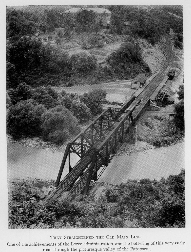
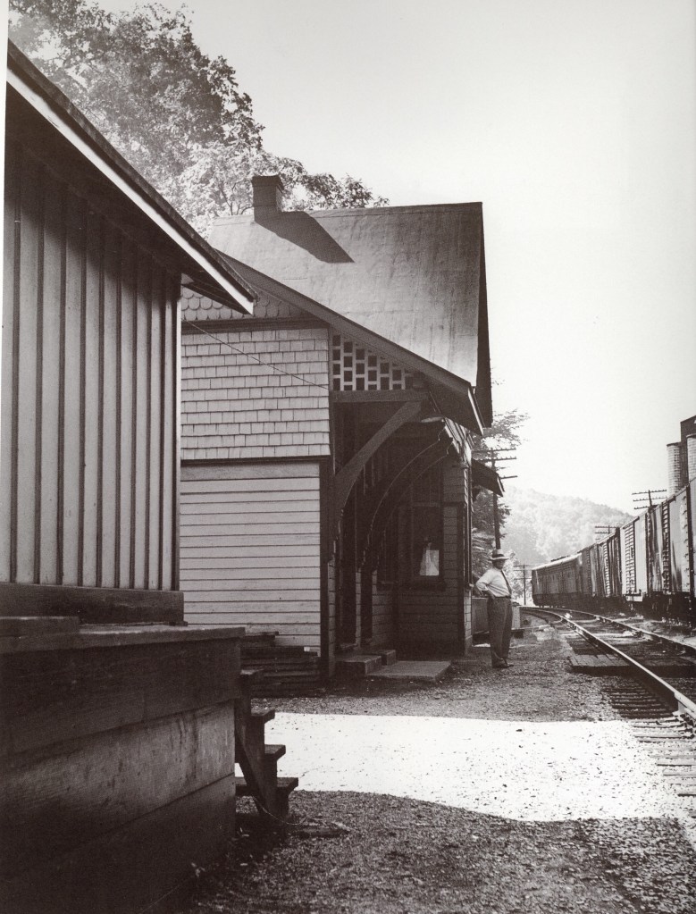
My 1950 Old Main Line (OML) layout needed a Mike for the local or peddler freight. Most of the time a Q-7f was assigned to this duty. Modeling this engine is difficult as it has only been produced as a brass HO model by Precision Scale a number of years ago. They now sell for well over $700. I have one now that I am modifying to look like #4844, which was photographed leading the peddler in my era. B&O Q-4 Mike locomotives were photographed in my era as replacements for #4844 and it seems reasonable that a B&O Q-3 Mikado may have also been assigned to this service when needed. My trusty old Broadway Limited Imports (BLI) USRA Light Mikado was one of the first Mikes to pull the peddler freight on my layout version the OML and has served well. This locomotive has been the main test engine for my layout, if it could make it through a turnout or curve, I hoped everything else could also. Most of my steam for my Old Main Line layout will be Mikes, mostly brass Q-4 and Q-7f models as that what was present in 1950. Through freights will also sometimes be handled by early diesels.
With this BLI model getting older, the drivers slipped out of the track a lot due to sideplay, so it was a good test for bad track work. And I ran it many times through new turnouts, curves, and testing operations, in fact, after it recently derailed through a new crossover, I took it to the work bench to look underneath. The plating has worn off a driver or two, the springs appear to have disintegrated, and the bearings are loose enough to allow a lot of sideplay on the main driver. Fortunately, these models are available on the secondary market and for less than $200 I was able to replace the entire drivetrain. The stock decoder had some glitches and my JMRI programming track couldn’t overcome them after repeated resets. So, while I was at it, I took the opportunity to replace the stock DCC and sound equipment with a Soundtraxx Tsunami2 TSU-2200 Steam 2, a Soundtraxx 810140 CurrentKeeper, and upgrade the speaker to a Scale Sound System (SSS) Force Full Range speaker. I chose the SSS 12mmx25mmx25mm, FFST -1225-RC1 to get the biggest speaker box possible into the tender.

I was apprehensive about touching the DCC and sound in this model as while it is not the greatest DCC sound decoder available today, it never failed to at least run in over 20 years of service. But all that running took its toll on the model and probably the electronics, so maybe it was time for an upgrade. The drivetrain seems to be relatively universal to any similarly aged version of this BLI model, so I sought one on the second hand market, hoping to just switch the drivetrain on my B&O detailed boiler shell and possibly using the same tender.
The second hand locomotive I purchased was about the same vintage and decorated for the Texas and Pacific (T&P). It was advertised as having DCC/Sound, but when it arrived, the tender only had a set up for DC, no decoder or speakers. The seller refunded me some funds to purchase speakers and I figured I was eventually going to update the decoder, so no time like the present.
I always knew I would update the DCC/Sound unit someday, along with other detail upgrades. This was a future project that became a “now” project as I wanted to have a simple, reliable locomotive to test my growing layout. And when you start taking things apart, it is hard not to upgrade them to your vision of “good enough”. But I will share the detail upgrades in future Part Two post.
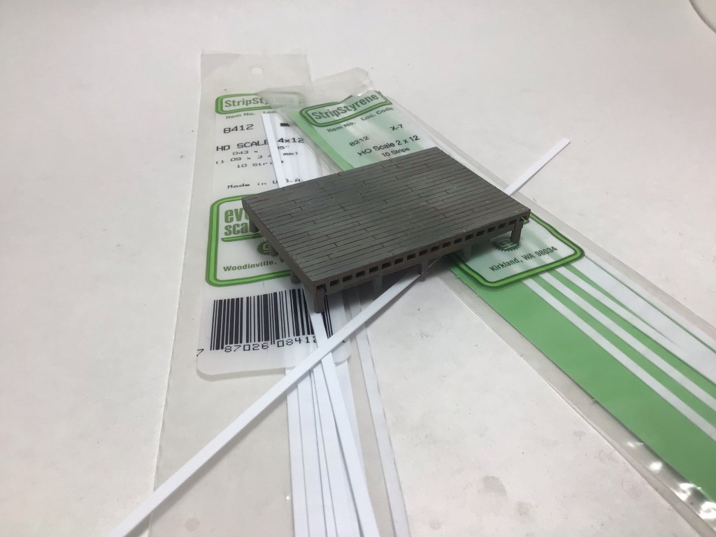
I was able to reuse the wiring harness and traced every wire back to its origin in the boiler and made the connections in the tender electronics through the original wiring harness. I did add a short piece of black shrink tube first to make the tender to locomotive connection look like a black pipe, possibly representing the stoker. The key to the easy installation was having the right parts. They all fit easily onto the tender base. I made a raised platform from styrene about 3/8” high on the rear of the tender base behind the speaker to mount the decoder and capacitor to avoid fouling the original connections to the trucks. The main purpose is to allow easier access for future maintenance. I’m sure I’ll have to replace or adjust something in the future if I keep running the engine, which is the goal!
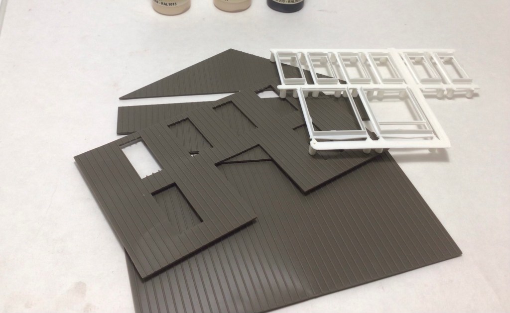
One of the big obstacles to recreating a later era B&O Q-3 is the addition of front end brakeman’s seat on the fireman’s side of the cab. I want to mention that I hope to be working with a fellow modeler to create a printed cab to fit the BLI USRA MIke. The original cab is a friction fit and I was able to replace mine with a resin part that has not been available for many years. Hopefully a new part will be available soon if you are thinking about a BLI USRA B&O Mike for your collection. Let me know if you have interest and I will pass that along.
I will end this post with a short video of the Mike in its half finished state, but with its sound system complete. I believe the SSS speaker and Soundtraxx sound decoder make a big difference that is audible in this iPhone SE video. I hope you agree!


