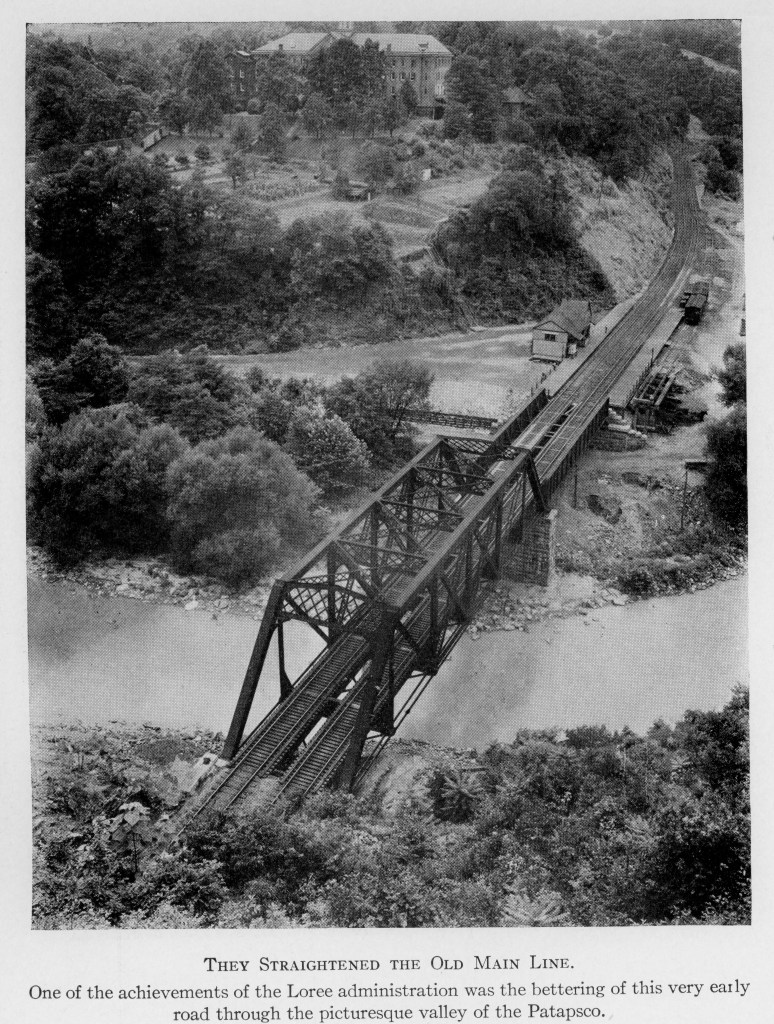
This part of the Ilchester railroad infrastructure seems to be fairly short-lived, it was around in my era of 1950, and very camera shy. It appears in parts in only a few photos I can find after years of searching. It is the raised Freight House on the left side of the photo, railroad east of the station. The B&O always ran east to west and always had a north side and south side of the tracks, regardless of what a compass indicated. On the B&O, Washington, DC was not south of Baltimore, but west.
August, 1952 photo of Ilchester Station and Freight House, B&ORRHS Photo Collection.
This might be the best picture that exists and it appears to be from August 1952 according to one caption. The board and batten siding and peaked roof are not things found on many eastern B&O structures.
My guess is that this station, its freight house, and coal trestle were originally built to serve the local community. Baltimore had some of the earliest “suburbs” in the nation. Areas like Roland Park were built in the 1890s and even had one of the first shopping centers. It was served by street cars and I suspect it served as a model for future possibilities. Pure conjecture, but early photos of Ilchester show long wood passenger platforms on both sides of the rail along with the coal trestle that could serve local coal deliveries. I wonder if the B&O thought Ilchester could become the next suburb served by passenger trains into the city? The station and infrastructure were built after the 1903-05 realignment, maybe adding the station was hoped to serve more than the boarding school or convent on the top the hill behind the station. The history of this area is not well documented and the effort of several modelers have served to add to the knowledge base. County historians look to fellow B&O modeler John Teichmoeller for definitive information about this community.
Photograph origin unknown.
Ilchester, MD 1941. Herb Harwood Photograph, B&ORRHS Collection.
How to model this elusive freight structure? Photos show board and batten siding and the building on a raised platform. The overhead view shows a peaked roof structure about 1/4 the length of the station and half its width. Their are standard B&O plans for a 16’x 20′ freight house, so maybe that size is appropriate. I know modelers build on less information and this may be all I ever find, so that’s what I am going with. On the up side, as soon as I complete the structure we all know a new photo will turn up. If so, at least the historical record can be set straight and I’ll have another structure to build.
There is a similar freight house at Dickerson, MD on the Metropolitan Subdivision and I used photos of it to supplement the photos of Illchester I found.
Dickerson Freight House and Station on the Metropolitan Branch. Underwood Photograph, Barriger Collecion.
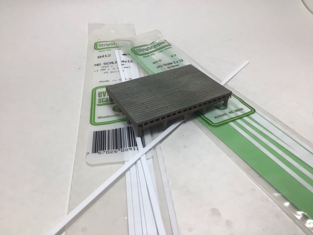
Using the rough dimensions from the overhead photo, I constructed the 15’ x 24’ raised wood platform from an old plastic kit from an unknown manufacturer. It was very close to the construction and dimensions of the platform in the standard B&O plans book available from the B&O Railroad Historical Society. The plastic kit was supplemented with scale Evergreen “lumber” to enclose the lower part of the structure which was painted a dark grey/black brown.
The platform from a very old kit, and Evergreen dimensional “boards” to enclose the platform.
The steps were from an old Campbell kit, but these are easy to replicate with styrene or scale lumber. They were painted the same color as the platform.
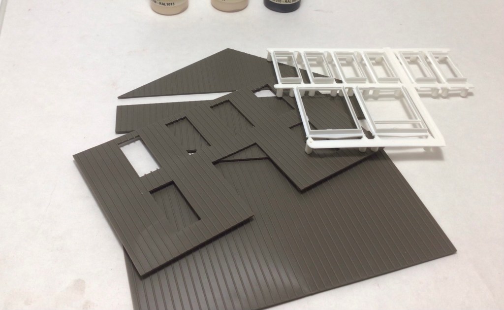
For the structure, I found another very old kit at a train show that had lots of board and batten sided parts along with a bunch of windows and doors for future projects. It took a while, but it’s always good to have something inexpensive to find at a train show or new hobby shop.
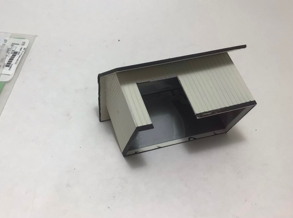
I cut the siding pieces to create 23’ x 12’ structure with a 8’ x 8’ opening for the door. The door is Evergreen styrene scribed siding painted the same black as the trim. The roof is .060 Evergreen styrene and I matched the roof pitch of the station building to mimic the photographs. The base trim boards are Evergreen styrene strips.
The roof is .060 styrene with the edges painted black to represent the trim boards.
The roof was covered with faded black construction paper to simulate tar paper roofing.
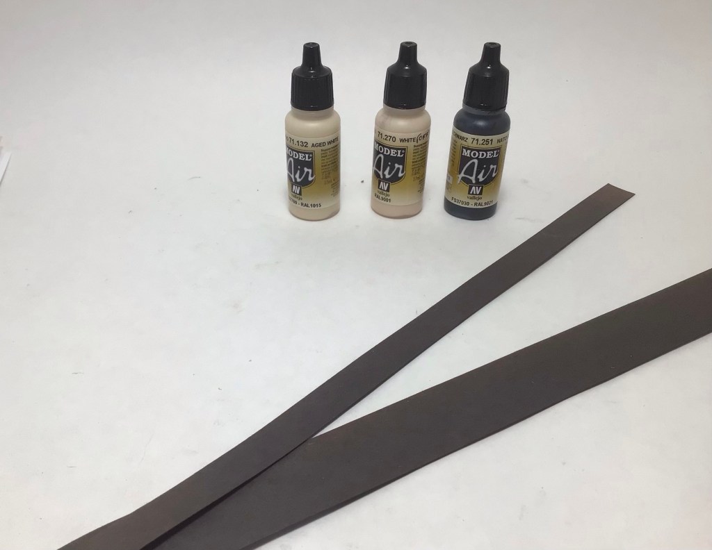
I used the same paint colors as those on the station for my rendition of the Cream and Black colors I remember seeing on old structures painted in this combination. It also matches favorably the Cream color shown on a 1939 paint chip card I received in an email some years ago. To match it, I airbrushed Vallejo Model Air 71.270 White (it is not a pure white) mixed with 10 drops of Vallejo Model Air 71.244 Sand Beige added to the almost full bottle. For the Black trim I used Vallejo Model Air 71.251NATO Black, it is a weathered flat black that has a slight brown hue that matches my recollection of the color.
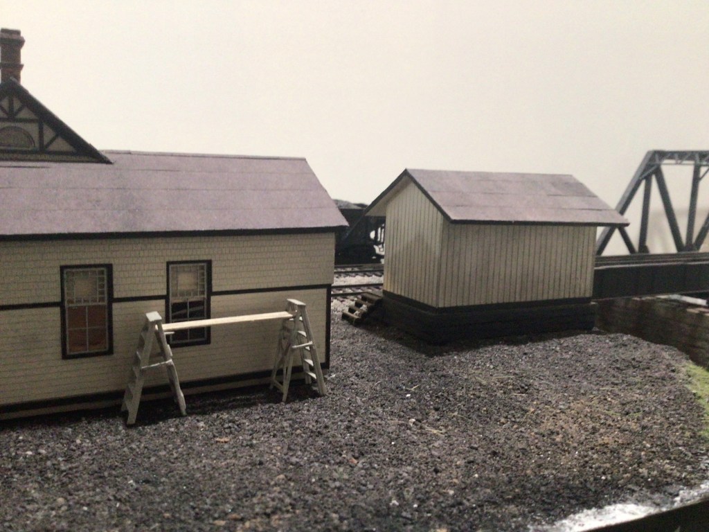
Looking across the mainline tracks at Ilchester from the north.The back of Ilchester Station and Freight House looking north from the parking lot. I added the freight agent as he appeared in the first photo of this post. Detailing the figure was covered in an earlier blog post.
B&O M-24a or b “Cement Car”. Paul Dunn Photograph. B&O RR Historical Society Collection.
This is a quick blog post so that others faced with a similar dilemma can see if they can use my techniques to shift the factory applied paint on their Rapido USRA B&O M-24 boxcar. I have several other blog posts and models I am working on, but this was an unexpected issue that came in the mail with my factory ordered model. I expected a brown boxcar to arrive and when time allowed I would change some lettering to reflect a ten year old boxcar on my layout set in 1950.
When the car arrived along with a Midwestern road version that I was really after to serve my milling plant, I took a few minutes at lunch to add some black and gray pin wash to both cars. The finish was glossy enough that I thought the technique could work straight out of the box, no gloss coat required.
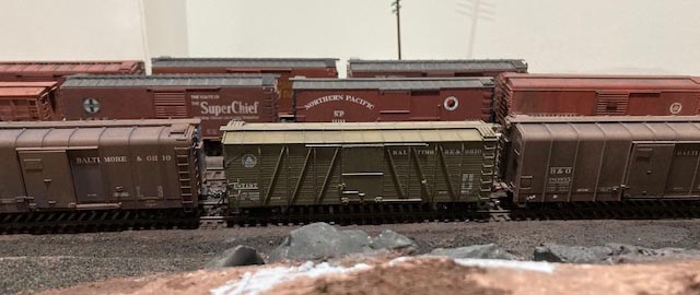
The Rapido model is between two other commercially available B&O freight car brown boxcars that are close to the color seen in prototype photographs from the era. The only alterations to the Rapido car are some black pinwash on the simulated metal parts on the sides and ends. The other cars have been sprayed with a clear matte varnish over black and dark gray pastels. The photo was taken under 5000K LED bulb lighting.The same model photographed in natural sunlight with the same slight weathering.
The pinwash did work and since I was was working near a large window, I had lots of sunlight to assist. This environment made me look closer at the color of the B&O car and I was convinced it was more green than brown. Sort of an US Olive Drab Green. I took some photos. And then when I got home I put it on the layout next to other boxcars of all kinds and to my surprise it looked even more green. I know lots of people have some type of color blindness so I thought that’s what I was seeing. But it was definitely different and didn’t come close to any of the B&O brown boxcars I own, either commercially painted or those I painted myself. I took some more photos on the layout under 5000K LED bulbs and shared them with a few friends who model the B&O and look at colors critically. They agreed that it was green I was seeing. For context, let me add that B&O boxcars of that era were painted a very average brown color until the mid 40s when a much more red freight car red was introduced. That later color is the color many see in color photographs of 50s era B&O boxcars. These changes in color also go along with changes in lettering. These were detailed by Chris Barkan and this information is available on the B&O Railroad Historical Society website. And to make it more difficult to know a true color there are not too many color photographs of the older brown color.
A relatively unweathered B&O boxcar in a 40’s era Jack Delano photograph. Library of Congress Collection.
I should have stated this up front and it is very important to say. I am not, and I repeat not, someone who focuses on exact color matches and original drift cards in my modeling. But, I do expect that when I purchase a well detailed and accurate prototype model that the color be close to the prototype. I don’t know the correct color for every model I buy and I trust the manufacturer of a high end product to get it close. This was not close by my standards for a B&O boxcar, but it may be fine for many others.
So what to do? I am aware that the manufacturer worked with the BORRHS so I assume they did their due diligence, so I wouldn’t expect a refund or a new model. Things happen. I looked at this as an opportunity to learn a little more about the color wheel and see how I could make this model match the other cars in my B&O car fleet. Many of the other cars in my fleet are Rapido, so this is not an indictment of their efforts. I certainly appreciate all the steam era models they have brought to the marketplace and support their efforts as much as I can.
So learning a little more about the color wheel and using techniques shared with me on the Real Steam Freight Cars .IO group, I decided to try to tint a matte overspray with a color that would shift the color of the car closer to what I believe is appropriate for a B&O boxcar painted in the late 30s or early 40s. I assumed this era based on the stenciling recreated on the model. As I detailed in a previous blog post, I now use Winsor and Newton Galeria Matt Varnish (I switched from Dullcote for performance and economic reasons, see previous blog), which is water soluble and can mix with the Vallejo Model Air colors that I choose to use.
I loaded some Matt Varnish in my airbrush and added a few drops of Vallejo Fire Red and less German Red Brown (about 5 to 1). I sprayed it on some white paper to see how much red brown would be applied to the model. I chose a red brown mix as that is opposite green (blue and yellow mixed) on the color wheel and should mute out some of the green in the boxcar’s appearance. It took two coats and the overspray turned the white lettering pink, there was a fair amount of red in the tinted matte varnish.
It might not have been the best solution, but I was trying to save myself from having to repaint and decal the model, so I used a microbrush to quickly wipe off some of the overspray from the lettering while it was still wet. It worked for the most part, but up close (last photo in this post) you can see where the overspray was wiped off of the car body outside of the lettering. Hopefully it’s not too noticeable, but it did cause me to go a little heavy on the weathering. Not inappropriate for a ten year car, I hope.
The result of the tinted matte overspray next to a more weathered model shown in the previous photo. This photo is also taken under the same 5000K LED bulbs I use on my layout.
These are the colors I used to tint the matte varnish. The Fire Red was added about 5 drops to 1 drop of the German Red Brown to the paint cup of Matt Varnish.
I added some paint failure spots on the roof with gray paint, blue washes and assorted colored pencils, then weathered it with black pastels to simulate soot and a hard life in the Northeast. The sides were lightly sprayed with a gray/black tinted matt varnish to add some lighter weathering to look softer, but similar to the roof.
The last details I add were new decaled reweigh and repack stencils closer to 1950, some faded chalk marks with sharp colored pencils, and a couple of brighter chalk marks with decals. I added spots of Pledge for a gloss decaling surface where needed for decaling, then after heavy doses of Walters Solvaset, covered the decal spots with matt varnish and some gray chalks to fade them a little. The trucks and wheels were sprayed with Vallejo NATO Black like most cars on my layout. The couplers were replaced with Kadee #158 scale head couplers. I still need to add some rust paint to them.
I hope this provides some helpful information to others and allows them to rescue this model or others using similar techniques. I certainly wasn’t expecting or relishing this challenge, but in the end I learned some new things and ended up with a model that fits my layout well. That’s got to be worth something!
This is the finished model on my layout. The color is very close to the brown freight color I would expect.The model depicts a car painted in the late 30s or early 40s as it might appear in 1950 without a repaint.
And here is a roster shot of the finished model in higher resolution.
The two track DCA yard is behind Tracks 1 and 2 of the Old Main Line just east of Ellicott City, Maryland. The short bamboo sticks on the right side of the photo are a mock-up for tree locations. The can take a beating and will let me know if they will be in the way when operating the layout.
The last time I gave a photo tour of the first two modules in July, 2019 (link to previous post) there was a lot of plywood showing, no fascia, a little backdrop, and no construction on the next three modules leading into the return loop.
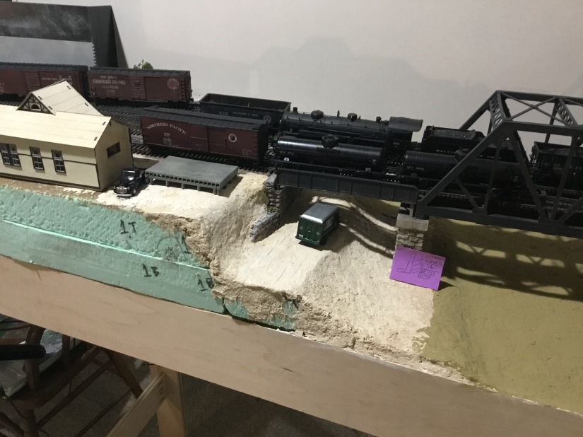
This is where we left off, the fascia needs to be added to give the station a little more real estate . And this is the same area in January 2022. Still some scenery to complete and a photo backdrop to add.
The Patapsco River in the first photo is dry, the station isn’t complete, and no fascia has been added. Since then I have finished the river, realized the Woodland Scenics Realistic Water material is a very thick fluid, even when “cured”, and is very, very slowly spilling over the edge of the layout. That will be a new project. The station is complete and mounted on a “concrete” foundation like the prototype after a later 40’s reconstruction project. I have started on the adjacent small freight house, I need to complete the roofing and the boards enclosing the raised platform. I will add a short blog on building that structure in the future.
I’ve been able to build four more modules and get the layout moved against the wall to allow the Ilchester Tunnel to reach staging in the unfinished part of the basement. One of the new modules is inline with the first two and the next three are set perpendicular to create the return loop that will take my Old Main Line back behind the backdrop to two modeled areas and then into the remote staging location and its return loop. This will allow continuous running.
You can see light at the start of the Ilchester Tunnel which is the staging in the unfinished portion of the basement. This January, 2019 photo appeared in my previous Pictures of Progress Blog. Only two modulars are built.This is the visible return loop at the Doughnut Corporation of America plant and will divide the layout into two halves. This is a view underneath the layout from the same end of the return loop. The original three modules appear at the far end.An Updated Layout Sketch. Sykesville has moved behind the backdrop and the Doughnut Corp. of America is no longer a hidden industry it is now a large, visible structure.
I was able to add fascia to about 40% of the layout. I used 1/8″ masonite as it can be bent to fit the curves of the layout. The layout is designed to follow the curving Patapsco River, just like the Old Main Line that was laid out to follow the river through gaps in the hills and mountains west of Baltimore. I wanted a smooth finish so I used Bondo Glazing and Spot Putty, it is a one-part product, don’t use the two-part product that is too hard to sand similarly to the masonite and is too thick for thin gap filling (two part glazing putty has a resin and a hardener like an epoxy, not great for this application). The Spot and Glazing Putty product works great on wood trim for the house also, it is red and hard to cover with paint, but doesn’t shrink over time and crack.
A joint in the hardboard fascia with Bondo Glazing and Spot Putty applied to create a smooth transition. After painting, the joint disappears and similar joints on the layout have gone through several season changes with no cracking.
I intend to build the very large Doughnut Corporation of America milling and manufacturing plant using an ITLA modular building system. I developed a mock up of the building that is less than 50% of the actual size, but it is large enough to portray the imposing size of the building. And it substantiates the need for a two track yard to serve it and the two track siding within the plant. It will be the primary operating feature for the 1950 Way Freight as it heads west every other day. And I presume it was serviced on all days, so it may be switched on the opposite, every other day east bound trip of the Way Freight. It was a priority customer over time, so it might have even rated a special train from Baltimore when needed. I need to find some more contemporary operations sources.
The mock-up of DCA using ITLA actual-size paper templates.Laying the mainline tracks headed into the curve past DCA that heads into Ellicott City, MD on the prototype. The mainline tracks are to the right, with the two tracks on the left serving the DCA plant.Switching west of the DCA plant in 1952. At the top right of the photo, one can see the bridge leading into DCA. The left two tracks are the mainline, the two on the right are the small yard serving DCA.
Behind the backdrop of my peninsula layout is the second half of the visible layout of the Old Main Line. Beside Ilchester, my favorite layout element is Sykesville, Maryland. I was based from the old passenger station in Sykesville when I worked on the track gang during summers in college. The base for the Life-Lke Main Line station injection molded plastic kit is seen in the photo below in an approximate location. It was modeled after the Sykesville Station and I bought one when it was released many years ago, knowing I would have a spot on a layout someday. I haven’t planned out the entire area and need more information about Sykesville in 1950. I need to build the station next and would love to have a color photo of the station from the 40s or 50s, if anyone knows of any, please drop me a message.
The visible layout behind the backdrop. Sykesville will in the first location on this side of the peninsula, further along before going through the wall into staging will be Gaither Tower and passing siding.
Finally, I decided to “brand’ my layout by developing a name for the layout, calling it “the Original Old Main Line” referencing it’s setting on the B&Os Old Main Line, the original part of the United States’ first common carrier railroad.
“The Original Old Main Line” logo. Developed using the B&O’s “Linking Thirteen States” logo and matching the unusual lettering style. Bruce D. Griffin Artwork.
A short video overview the layout progress.
Getting closer to the photo below, needing a backdrop with trees and some 3D trees on the granite above the tunnel portal.
The station has been abandoned in this 1960’s era photo. Bill Hopkins Photograph.
I have written before about my switch to acrylic paints, specifically Vallejo paints for airbrushing. To keep down the mess in the house, I wanted a cheap, lightweight spray booth with lots of light and an exhaust system for the particles and slight odor. I have been airbrushing inside with a cardboard box and using a respirator to catch particles before the entered my body. It had its limitations.
The Old Cardboard Box Solution.
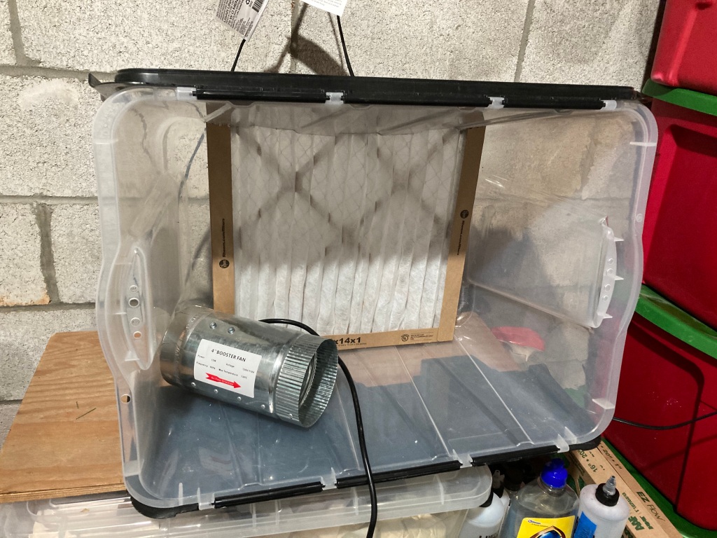
I started with the idea of using a plastic storage crate about the size of my cardboard box. The plastic was hard to work with as it was brittle and my search for an inline exhaust fan didn’t work out. I was hoping the clear plastic could help with lighting inside the booth, be lightweight, and portable for future moves.
The Original Paint Booth in a Storage Crate Idea.
I live on top of a large granite and marble deposit, one of the revenue sources for the NCR that run through this area starting back in the 1830s. These deposits off-gas low level radiation, so my house is fitted with a radon removal system. It is basically a hole in the basement slab with an extraction fan outside of the house to pull the radiation up and away from the house. When I first moved in seven years ago, the exhaust fan on the side of the house wasn’t working, so I found the same fan model and replaced it. Just last month the fan started to vibrate, maybe a bearing was wearing, and it caused a reverberation throughout the house. A new fan was sourced for about $150 and the replacement (a new model number with slight design changes) ended the house-wide vibrations. Then I realized I had a fan that could pull 160+ cfm that works, but with a slight vibration. Paint booth dreams were again alive. And one big advantage is this fan is that it is meant to connect with 4″ PVC pipe and easily adapted to use flexible, metal 4″ dryer hose connections.
The main lesson that I can share from this experience is that lightweight construction is possible on a budget. A little time woodworking with a table saw can provide a strong frame and the walls can be thin and lightweight. Like the walls on the inside of a house, the framing provides the structure and the skin can be weak. Having enjoyed the size of my cardboard box, I used it for a start and created the main structural members from 3/4″x 2″ poplar. You can use another wood, but I was lucky to have access to some hardwood stocks that a friend was willing to share. I created two 18″x !8″ frames for the sides and used half-lap joints with glue, then a light spray to polyurethane to seal the wood. A glued half-lap joint is very strong and provides the main structure for the booth. The width between the two sides was determined by the width of a roll of easel paper. I saw this online, someone used a roll of drawing paper hung at the top, back of their paint booth to allow for a renewable white background for painting and possibly photography. The rolls are available through Amazon and much cheaper at many craft stores for $6, they are used for children’s art easels.
Gluing Half-Lap Joints on Side frames.A Light Coat of Polyurethane on the Side Frames.
For the bottom of the box I used a thin piece of plywood lying around in the garage. It was 1/4″ pine, which helped with keeping the box light. I added a second piece of 1/4″ under the front lip for dimensional stability. My second choice was a piece of 1/2″ birch plywood left over from layout framing. The width was 20″ to allow for the paper roll to fit within the side frames. The depth was set at 22 1/2″ to give me a little lip on the front of the box for paint bottles, cleaning supplies, and the spray-out pot I use to clear my airbrush. The side frames were screwed from the bottom of the plywood base. I skipped glue here in case I want to take it apart or adjust the size. The added a lip also gave a place for the paper roll to be slid under and secured.
The Paper Slides Under the Lip.
I wanted the top to be clear or translucent to allow light to enter the box and possibly add lighting from outside the box. I was leaning toward buying some plexiglas to cover the 20″x 18″ top of the box. I didn’t need a solid piece of plywood like the bottom foundation, so I was thinking of just using some 20″ wide scrap strip to the keep the sides from moving too much with the plastic to fill the space. Once again a scrap piece of material came to mind. I had several 12″x 12″ pieces of glass from former wall decorations that I had saved to use for my modeling bench as replaceable smooth work surfaces. A couple of pieces of the poplar hardwood I received had reliefs cut into them so two 18″ pieces became the top braces, along with another scrap piece for the back edge. I was going to screw the glass in place as the pieces had holes in the corners, but I decided to use two more pieces of the same trim to capture them in place within a frame, a few thin screws helped hold this together and make it removable should the glass become to covered in overspray.
Top Frame and Light Opening.
For lighting I am using a simple metal, portable flood light sitting on top of the glass and two short screws into the cross braces to keep it from moving and stay above the glass. The light fixture is fitted with a 5000k LED floodlight bulb which operates cool to the touch and is the same bulb used over my layout. Do not try this with an incandescent bulb, they are way too hot and a possible fire hazard being in contact with cardboard and finished wood! The 5000k bulb should help with having the paint applied in the booth look the same as it would on the layout.
LED Light Fixture in Place.
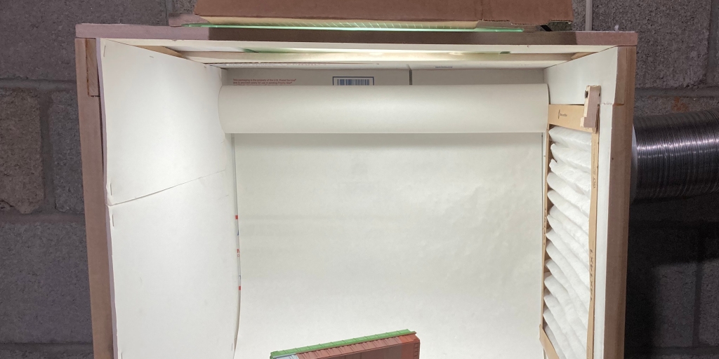
A simple dowel was used to hang the roll snugly between the sides. I mounted it as high and as far back in the box as possible. The roll I bought is 75′ long so I need to remember to buy the same size in a few years as I have seen much longer rolls with larger diameters available. The cardboard used for the back wall is visible.
Adding white cardboard or foam-core is just the covering for the back and the sides, it provides no structure, but keeps the negative pressure pulling air from the front of the booth (where is protects the user) and white allows for better light reflection inside the box and thus more light on the paint subject. It is just stapled in place so that it is easy to replace. We’ll see how this works over time.
The radon fan needed a mount as in its primary use it is attached to braced 4″ PVC pipe with rubber collars on the outside of the house. (insert photo of fan outside house). Here again I took advantage of scrap lumber, this time a 24″x 24″ piece of birch 1/2″ plywood left over from my layout’s modular structure construction. I built a shelf 10″x 10″ to be as wide as the fan and used a jigsaw to cut a 5″ hole in the center to allow the fan body to sit down into the shelf. To mount the shelf to the cinder block wall of my basement I cut a mounting bracket with a dado cut to fit the shelf and then added some angles from the shelf down to the bottom of the mounting bracket. I gave this a light spray of polyurethane to give it some dimensionally stability over time. After attaching the mounting bracket to the wall with three Tapcon concrete screws, I added a couple of drops of acrylic adhesive caulk to attach the fan housing to the bracket and keep it from moving around, while providing a soft mount to keep vibrations to a minimum. I only used a couple of drops of adhesive as I want to be able to cut the fan free should it fail in service.
The Assembled Parts of the Radon Fan Shelf and Mounting Bracket.
Venting the booth outside house is always a challenge. A window can be a great option. I didn’t have this option in the unfinished side of my basement. Then I caught a lucky break that not one in a million modelers gets, I found an unused dryer vent to the outside just seven feet from my intended booth location. It still goes outside and was plugged with expanding foam to keep out small animals. I can’t figure out why it is there, the washer-dryer is fifteen away and there are no nearby plumbing connections to suggest the washer-dryer had been moved at any point. I can’t help you if you are not that fortunate, but I can say the radon fan will push some air as it is sized to move a lot of air two stories up, so a longer run on the exhaust side of the fan is practical. Keep in mind this is only for use with non-flammable solvent paints and finishes, don’t try this with flammable solvent based paints!!! If it doesn’t clean up with water, I don’t use it.
A Fortunate Dryer Vent.
This is a design-build project, so I had a general sketch or two in place and set out to build it to meet the design intent with the materials on hand, adjusting as needed. And I am writing this blog as I am building it, so one of the last details to complete was how to connect the duct work to the side of the box. In the original plastic storage crate design I was going to use a 14″x 14″ filter in front of the fan connection at the back. I realized a side mount fan would be better for my new box design and allow the booth to sit closer to the wall and more out of the way. I knew this wasn’t a good a design to get the best laminar flow across the face of the paint booth, but with 160 cfm pulling through the fan, I was going to exchange all of the air in the box about once every two seconds. Adequate air flow shouldn’t be a problem. The plan was to put a 4″ coupling for flex duct on the top edge, near the back of the side nearest the fan and use some type of filter to protect the fan from paint particles. So far I have only invested time, as all the materials were on hand. I grabbed the 14″x 14″ inch furnace filter to see how I could attach it to a side frame or maybe consider something else. Serendipity struck again and the filter fits perfectly into the popular side frame opening. It was a press fit! I would like to say that was planned, but it was per luck. With the fan pulling through one corner of the filter, I actually think I can get four times the filter life as I will rotate it periodically to put a fresh corner of the filter closest to the fan intake. So next I attached a coupling connection to a 5″x 5″ piece of the 1/4″ plywood with a 4″ hole and…
Furnace Filter Press Fits into Right Side Frame
The finished box, now a paint booth, needed to be attached to the wall and/or held up on legs. I wanted the booth at layout height so I was painting models at the height they would be viewed. I decided to use some plastic shelves from Lowes that are 18″ wide. I attached them to the wall with 1-1/2″ conduit clips to keep it in place. It was a little top heavy. The $20 shelves gave me a place for paint and thinners. A nice bonus.
I connected the flex dryer hose to the connector and hit a few gaps with duct tape for some and caulk for permanent connections. I may add a piece of plexiglas across top front to increase air movement through the box. It pull the fumes away, but you can never have too much ventilation.
Duct Connection, Cardboard Sides, and Conduit Straps Holding it All in Place.
This was a fun project and added a little professional touch to my modeling. It doesn’t hurt to have nice tools and this one was low cost. Model on ya’ll.
The turnout shown in the back has only been treated with Micro Engineering (ME) Rail Weathering Solution, no paint has been applied. The foreground track is ME Weathered Code 83. The match is pretty good and I didn’t have to worry about cleaning off paint.
So I mentioned I spent some time as a Trackman on the B&O. That experience taught me that turnout ties were not often replaced at the same time as regular ties. Those standard ties were much more available for track gangs to replace and of course there are so many more compared to switch ties.
A prototype photograph from my modeling era about 2000 yards west from the spot modeled in the previous layout photo. The first two tracks are the mainline looking west to Point of Rocks. (B&ORRHS Photograph)
I mention this as there are some prototype reasons why switch ties look different from all the rest as far as weathering and condition. At least on a well maintained line. It is not unusual for the longer switch ties to all be of similar age, while the standard ties around them may vary in age. The standard ties are replaced as needed, while a turnout would be repaired more likely as a unit with most or all ties being replaced. This is a factor in weathering for a model railroad. The rail on the other hand may be laid at a different times, but it’s weathering for modeling purposes is more uniform as it lasts much, much longer than a wood tie. Although turnout rail is replaced as a unit usually also, the intervals are just much longer. A Track Foreman or Track Supervisor will gauge turnouts and oversee construction, a lowly Trackman can gauge other track and spike it. Speaking from experience.
My modeling project is using Micro Engineering products and the track I bought is pre-weathered, though the turnouts do not come pre-weathered. Based on my earlier statements, I believe I should weather the rail similar to most of the rail in proximity, while the ties can be less uniform, for good reason.
One way to weather rail is to paint, another option is to use a chemical “blackening solution”. I was satisfied with several applications of Micro Engineering (ME) Rail Weathering Solution #49-103 as it turned the turnout rails a dark shade and matches the pre-weathered rail ME offers. Older rail, before the advent of roller bearings on freight cars, weathered a dark, dark gray stained by the grease from wheel bearings. Rail in more modern times often has a hint of surface rust and brake shoe dust that makes it appear a lighter, more orange color. Except maybe near rail lubricators that keep it a more dark gray color.
The closer turnout has several applications of ME Rail Weathering Solution while the background turnout is straight from the package. The application is brush on.
If you zoom in on the layout photo (I did that below) at the top of the post you can see that I have added joint bars and cuts in the track at prototypical distances on the rails. I still need to add a little chalk weathering and finish the ballast details, but the track work is coming together. Its a detail that we often pass over and getting it to match your prototype can help complete the scene.
If you look close you can see the joint bars on each rail. I didn’t add bond wires to the joints.