The two track DCA yard is behind Tracks 1 and 2 of the Old Main Line just east of Ellicott City, Maryland. The short bamboo sticks on the right side of the photo are a mock-up for tree locations. The can take a beating and will let me know if they will be in the way when operating the layout.
The last time I gave a photo tour of the first two modules in July, 2019 (link to previous post) there was a lot of plywood showing, no fascia, a little backdrop, and no construction on the next three modules leading into the return loop.
This is where we left off, the fascia needs to be added to give the station a little more real estate . And this is the same area in January 2022. Still some scenery to complete and a photo backdrop to add.
The Patapsco River in the first photo is dry, the station isn’t complete, and no fascia has been added. Since then I have finished the river, realized the Woodland Scenics Realistic Water material is a very thick fluid, even when “cured”, and is very, very slowly spilling over the edge of the layout. That will be a new project. The station is complete and mounted on a “concrete” foundation like the prototype after a later 40’s reconstruction project. I have started on the adjacent small freight house, I need to complete the roofing and the boards enclosing the raised platform. I will add a short blog on building that structure in the future.
I’ve been able to build four more modules and get the layout moved against the wall to allow the Ilchester Tunnel to reach staging in the unfinished part of the basement. One of the new modules is inline with the first two and the next three are set perpendicular to create the return loop that will take my Old Main Line back behind the backdrop to two modeled areas and then into the remote staging location and its return loop. This will allow continuous running.
You can see light at the start of the Ilchester Tunnel which is the staging in the unfinished portion of the basement. This January, 2019 photo appeared in my previous Pictures of Progress Blog. Only two modulars are built.This is the visible return loop at the Doughnut Corporation of America plant and will divide the layout into two halves. This is a view underneath the layout from the same end of the return loop. The original three modules appear at the far end.An Updated Layout Sketch. Sykesville has moved behind the backdrop and the Doughnut Corp. of America is no longer a hidden industry it is now a large, visible structure.
I was able to add fascia to about 40% of the layout. I used 1/8″ masonite as it can be bent to fit the curves of the layout. The layout is designed to follow the curving Patapsco River, just like the Old Main Line that was laid out to follow the river through gaps in the hills and mountains west of Baltimore. I wanted a smooth finish so I used Bondo Glazing and Spot Putty, it is a one-part product, don’t use the two-part product that is too hard to sand similarly to the masonite and is too thick for thin gap filling (two part glazing putty has a resin and a hardener like an epoxy, not great for this application). The Spot and Glazing Putty product works great on wood trim for the house also, it is red and hard to cover with paint, but doesn’t shrink over time and crack.
A joint in the hardboard fascia with Bondo Glazing and Spot Putty applied to create a smooth transition. After painting, the joint disappears and similar joints on the layout have gone through several season changes with no cracking.
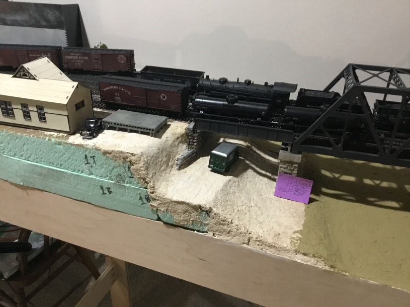
I intend to build the very large Doughnut Corporation of America milling and manufacturing plant using an ITLA modular building system. I developed a mock up of the building that is less than 50% of the actual size, but it is large enough to portray the imposing size of the building. And it substantiates the need for a two track yard to serve it and the two track siding within the plant. It will be the primary operating feature for the 1950 Way Freight as it heads west every other day. And I presume it was serviced on all days, so it may be switched on the opposite, every other day east bound trip of the Way Freight. It was a priority customer over time, so it might have even rated a special train from Baltimore when needed. I need to find some more contemporary operations sources.
The mock-up of DCA using ITLA actual-size paper templates.Laying the mainline tracks headed into the curve past DCA that heads into Ellicott City, MD on the prototype. The mainline tracks are to the right, with the two tracks on the left serving the DCA plant.Switching west of the DCA plant in 1952. At the top right of the photo, one can see the bridge leading into DCA. The left two tracks are the mainline, the two on the right are the small yard serving DCA.
Behind the backdrop of my peninsula layout is the second half of the visible layout of the Old Main Line. Beside Ilchester, my favorite layout element is Sykesville, Maryland. I was based from the old passenger station in Sykesville when I worked on the track gang during summers in college. The base for the Life-Lke Main Line station injection molded plastic kit is seen in the photo below in an approximate location. It was modeled after the Sykesville Station and I bought one when it was released many years ago, knowing I would have a spot on a layout someday. I haven’t planned out the entire area and need more information about Sykesville in 1950. I need to build the station next and would love to have a color photo of the station from the 40s or 50s, if anyone knows of any, please drop me a message.
The visible layout behind the backdrop. Sykesville will in the first location on this side of the peninsula, further along before going through the wall into staging will be Gaither Tower and passing siding.
Finally, I decided to “brand’ my layout by developing a name for the layout, calling it “the Original Old Main Line” referencing it’s setting on the B&Os Old Main Line, the original part of the United States’ first common carrier railroad.
“The Original Old Main Line” logo. Developed using the B&O’s “Linking Thirteen States” logo and matching the unusual lettering style. Bruce D. Griffin Artwork.
A short video overview the layout progress.
Getting closer to the photo below, needing a backdrop with trees and some 3D trees on the granite above the tunnel portal.
The station has been abandoned in this 1960’s era photo. Bill Hopkins Photograph.
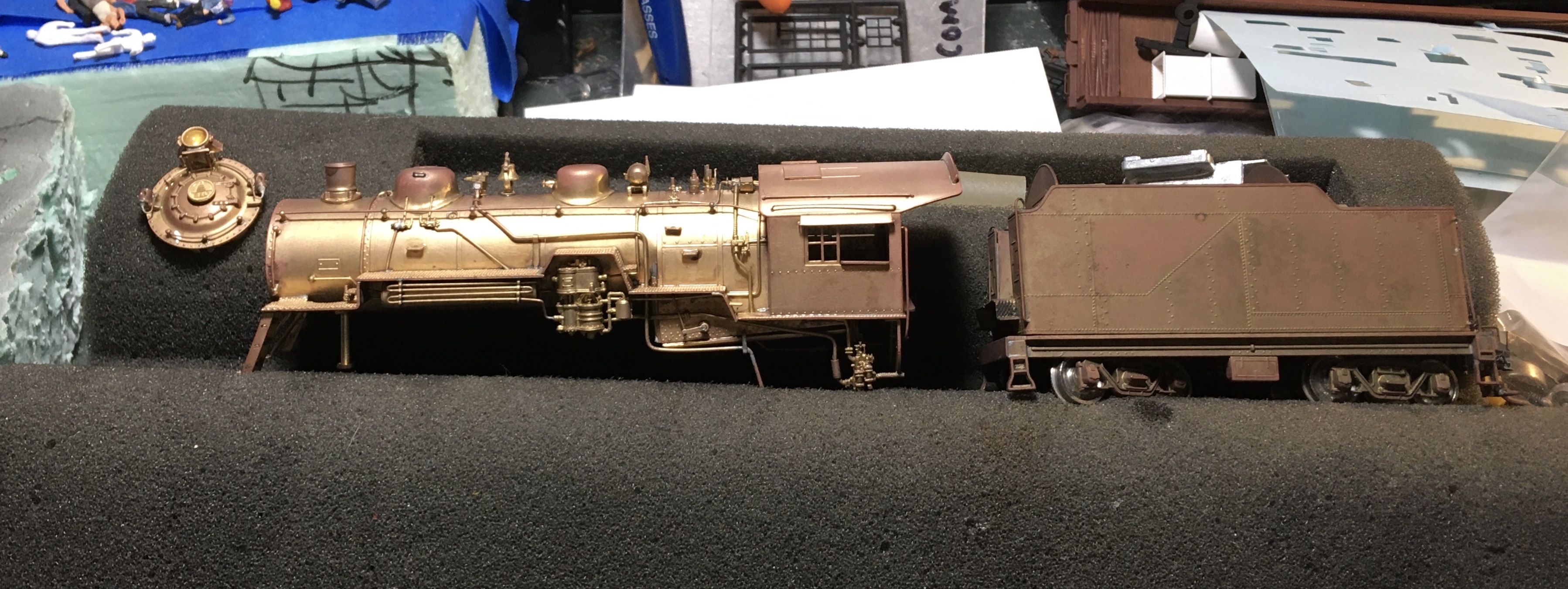
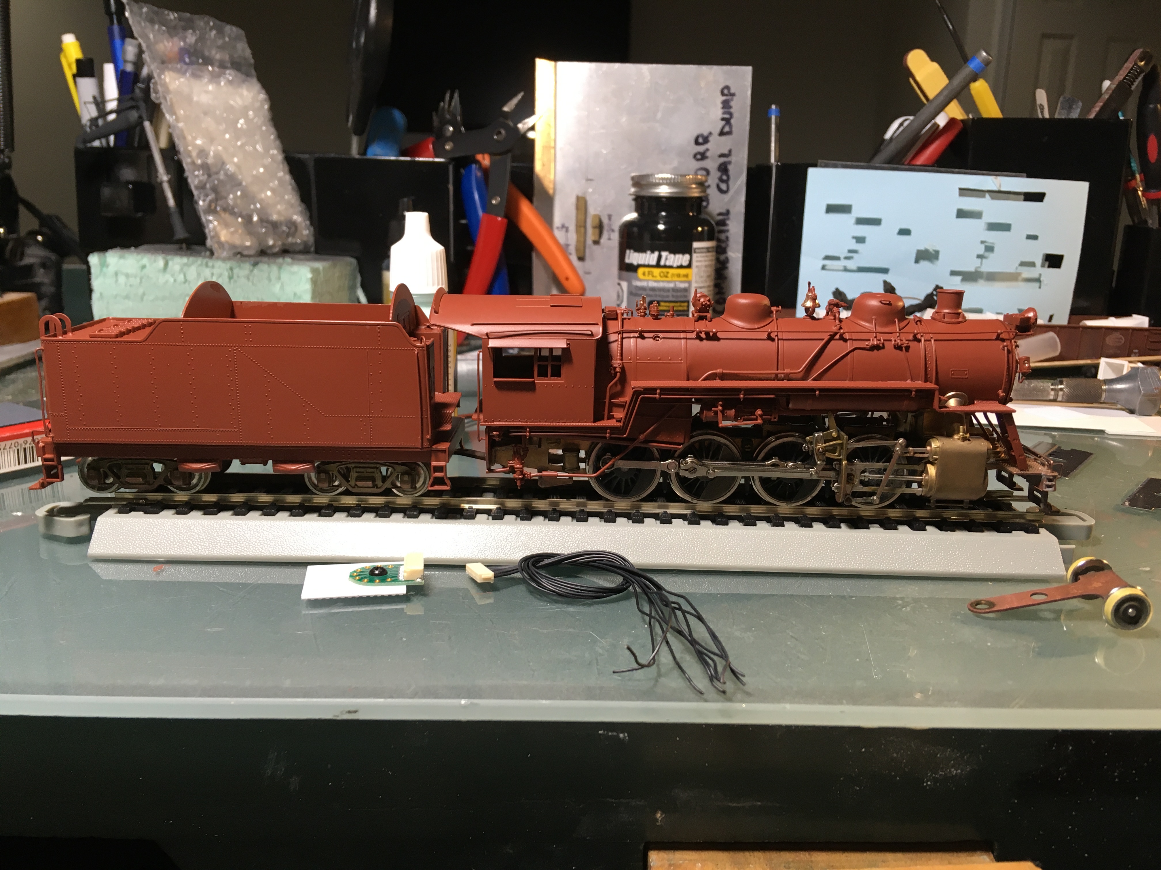
I am always looking on eBay for a bargain Q-1 or Q-4 Mikado to back-up the Q-7f that most often will run the Old Main Line Peddler on my layout. Recently I found an older PFM/United B&O E-27 Consolidation at a great price. It was tarnished and tired looking, but the drivers looked good, so I took a chance. This locomotive type was not often seen on the Old Main Line in the late 40s and early 50s but it would provide a great learning platform and test bed for me. I need to add DCC and sound to my brass Q-7f that is well painted and runs great. I am already adding sound and DCC to a pair of Life-Like Proto 2000 FA-2s as a test bed for future upgrades to my Kato and BLI F-units. That experience has shown me that “practice makes better” as I have already gained a lot of knowledge from mistakes made.
Photo of the model on eBay.
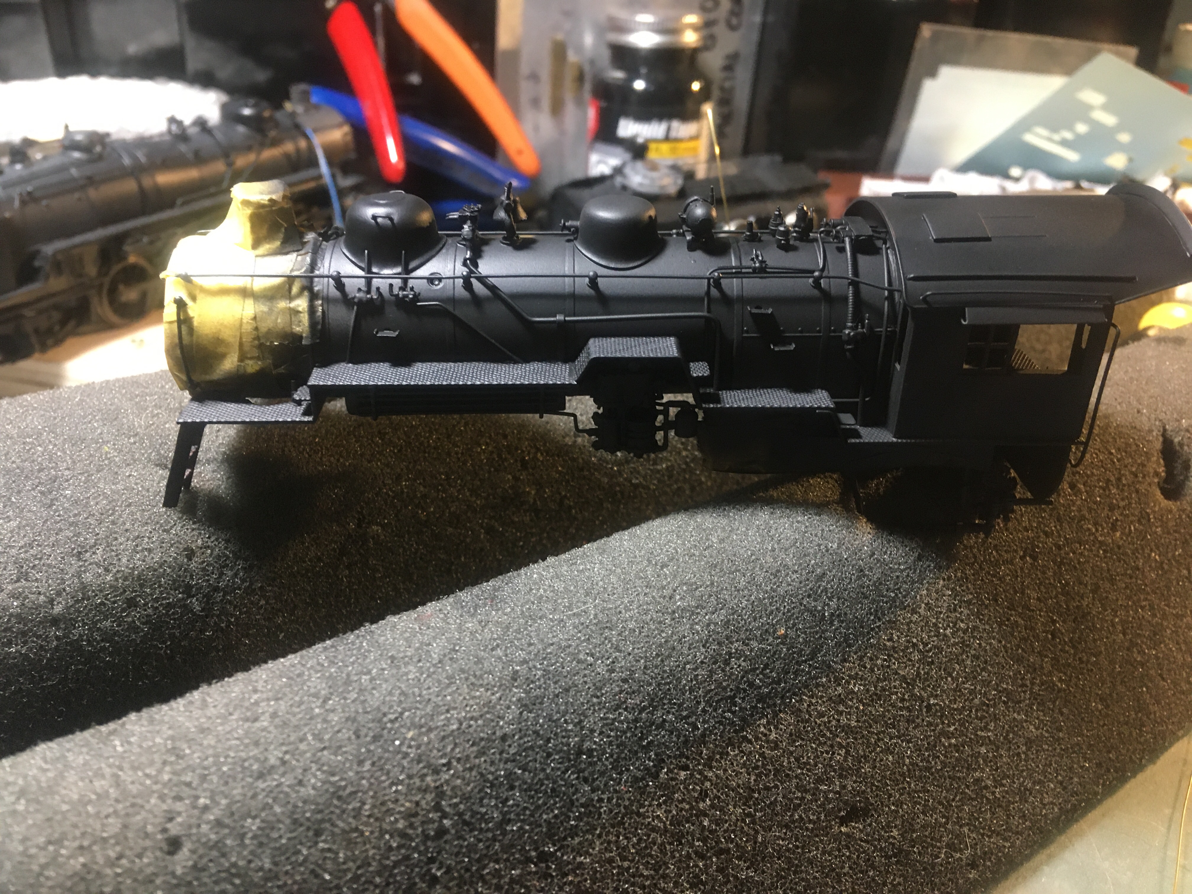
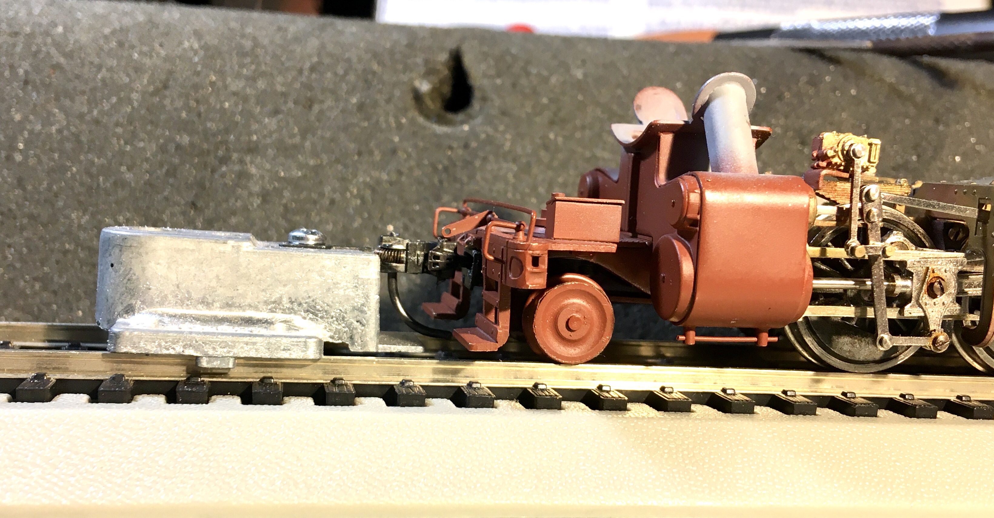
With a little bit of research I realized the tarnished boiler was not a big problem and I could media blast it with my $20 baking soda media blaster to smooth out the finish.
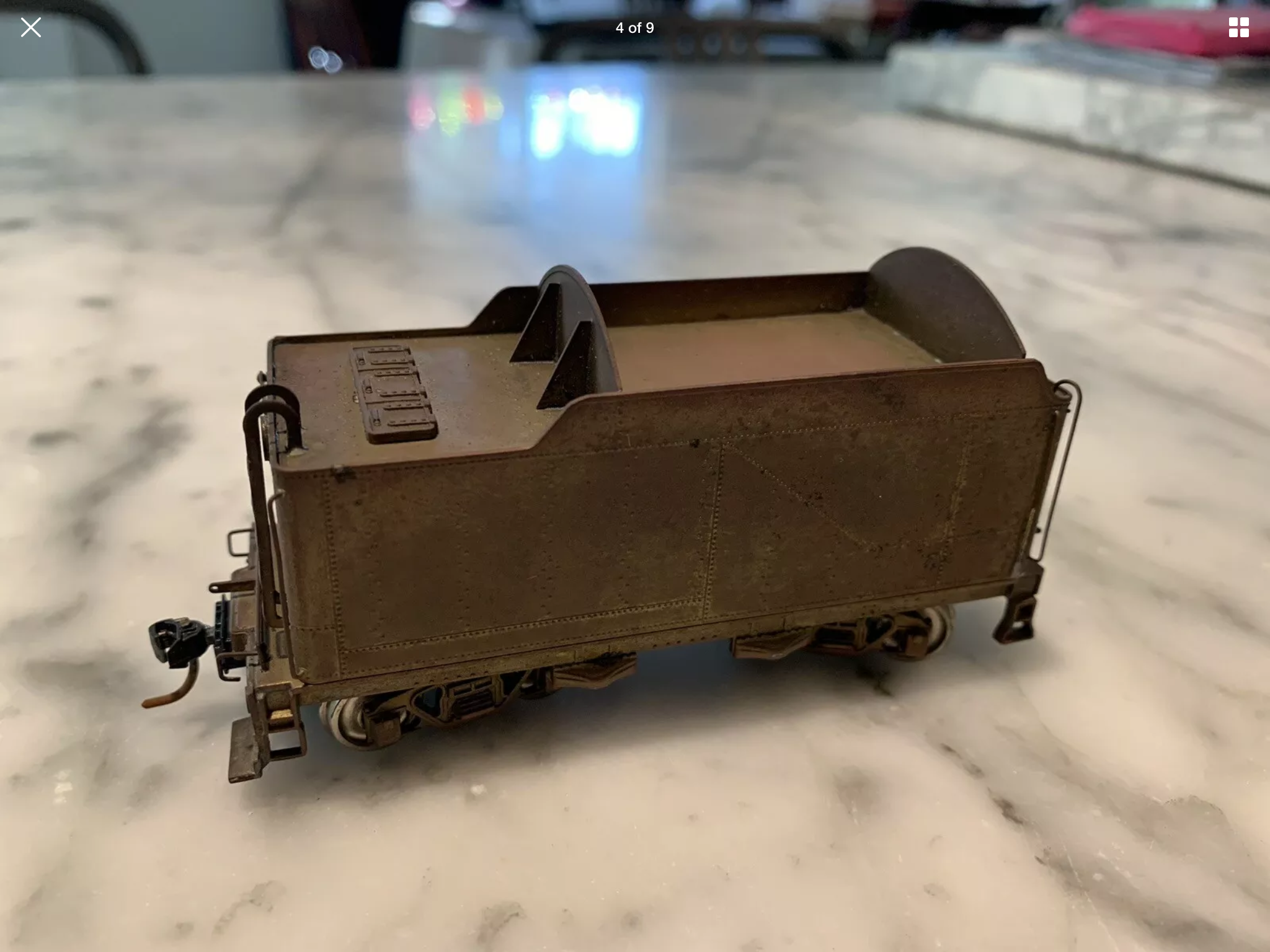
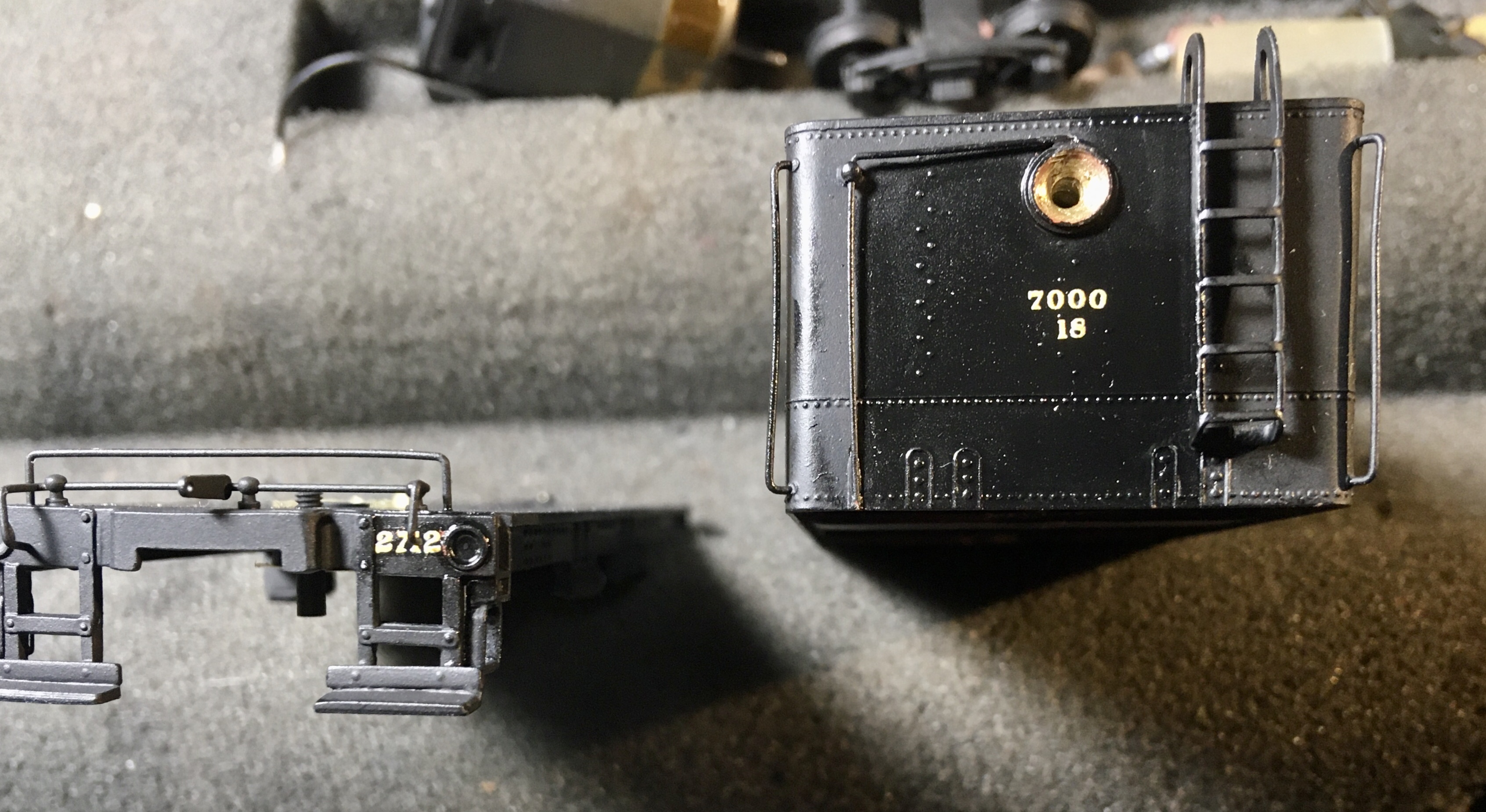
The eBay photo of the tender.
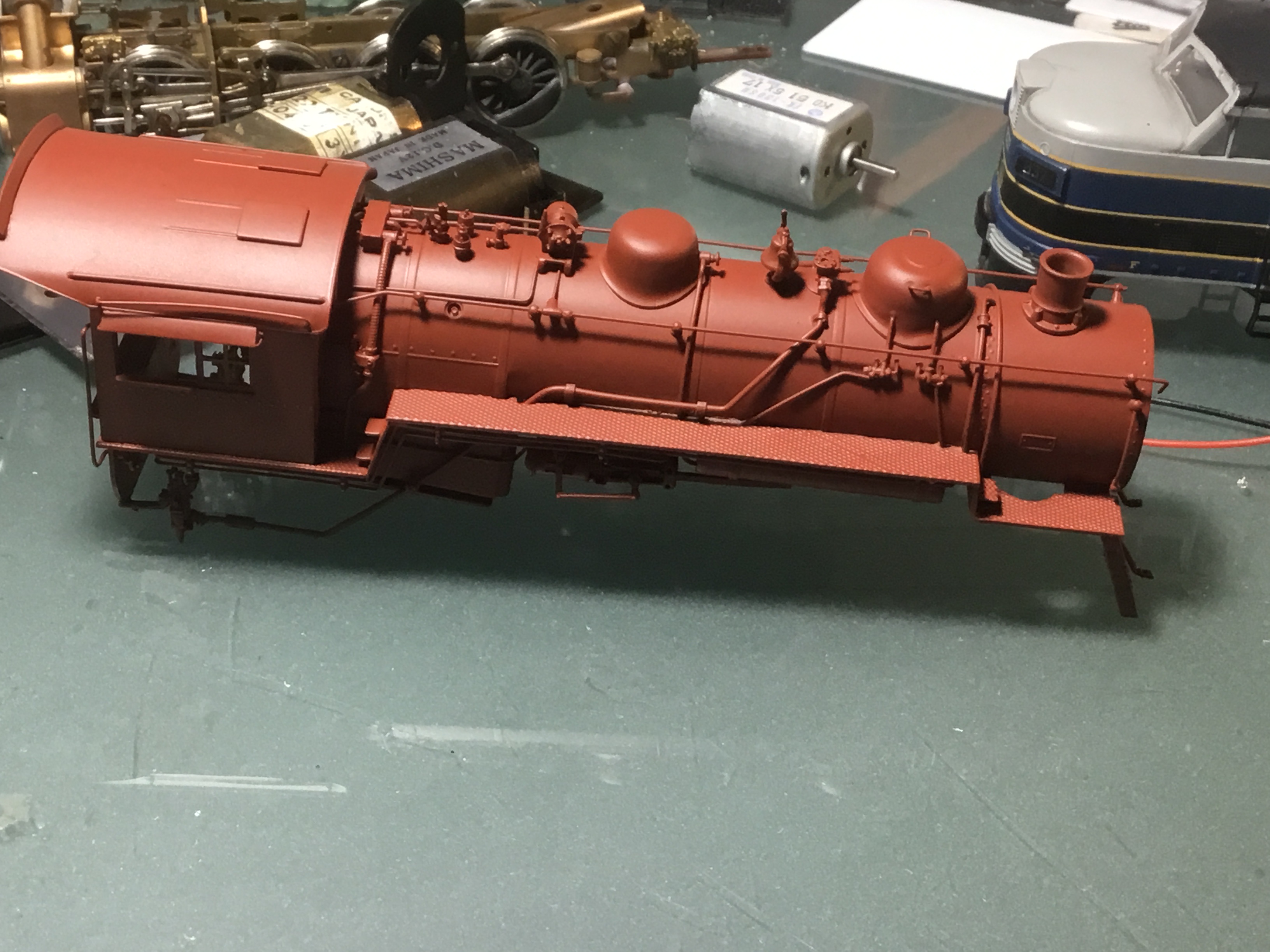
I disassembled the model, but left the drivers and running gear connected as I did not want to mess them up too badly by my lack of experience. After getting the major body parts away from the running gear, I blasted them with baking soda, gave them a hour bath in dilute vinegar, and then after dry, hit them with Tamiya red primer from a can. The frame and running gear was spared this abuse and cleaned with WD-40 300554 Specialist Contact Cleaner Spray, the same polar solvent I use to keep my track clean. It is a good solvent and supports clean conductive surfaces. It cleaned the grease and dust from the running mechanism and left it dry and easy moving. I little Labelle #108 light oil was used to re-oil the bearings and joints on the mechanism. I did this before painting to insure the joints were well oiled and as they are mostly hidden I did not worry about great paint adhesion.
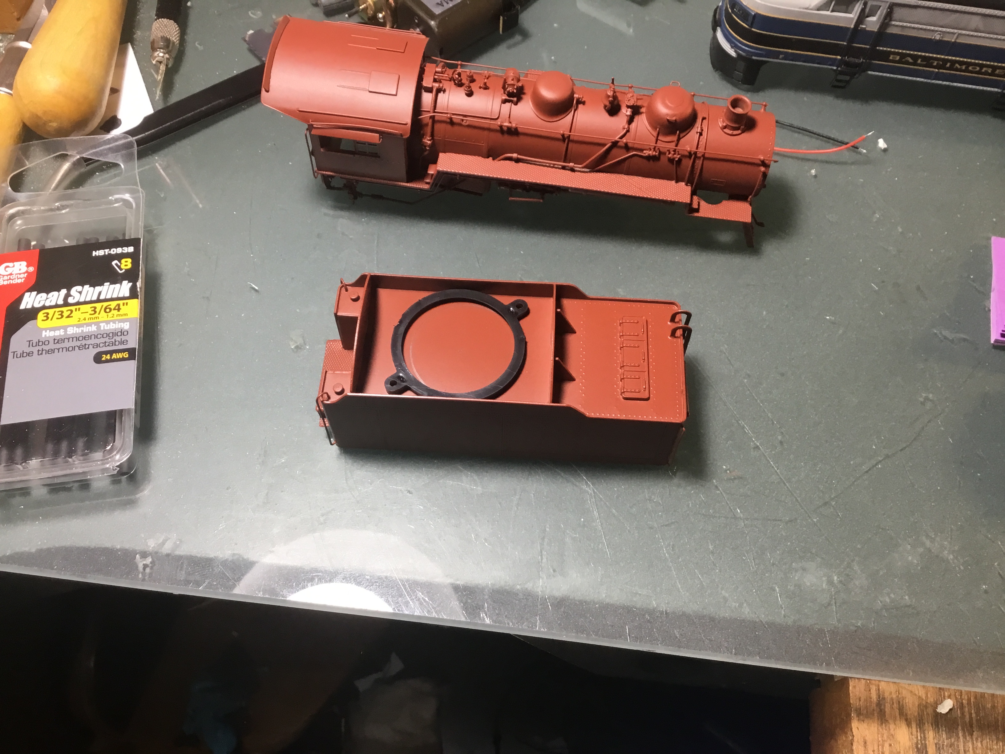
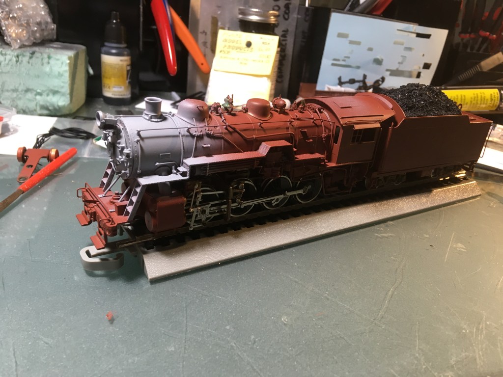
I started with the boiler and cab assembly, the difference is striking. The red primer looks garish, but it is a good base color for a black finish coat and the Tamiya primer gives a very fine finish compared to other spray can primers.
The mechanism rolls very freely after being cleaned well and lightly oiled.
I wasn’t sure if there was a lacquer coating or gold paint on the model, so I tested the base of the tender overnight in a paint remover and found no change. The vinegar bath did dissolve some type of topcoat as the solder joints became more visible. I have read that some modelers soak in a vinegar and water bath overnight, I used about a 25% solution for an hour and like the results. The metal is smooth and accepted the primer well for a very smooth undercoat.
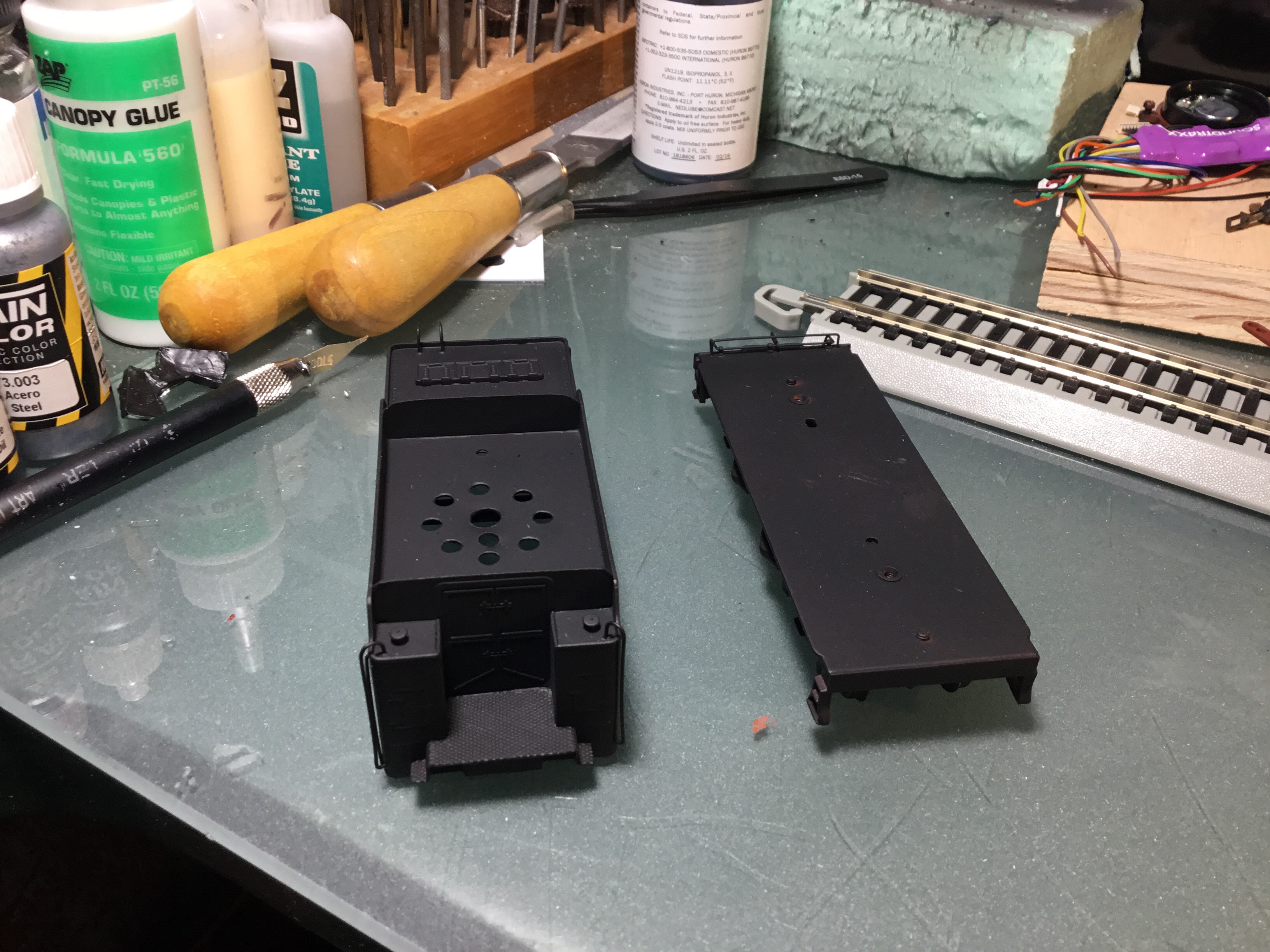
The tender received the same treatment. The black circle is a Soundtraxx speaker mount I am testing for size.
The tender will receive the bulk of the DCC and sound updates and there is enough room to add a capacitor to keep the locomotive running over any gaps on my layout track.
The one area that is least familiar to me is upgrading the motor, tuning the gearbox, and making sure the mechanism is as smooth as a Swiss watch. Other smaller challenges to the locomotive/boiler include adding lighting, a working front coupler, and possibly changing the air pump (I didn’t make this change). Knowing my weakness I put a request for help on the B&O listserve. The results were fantastic, more on that later.
When I am unsure, I start with the more familiar and for me that is now painting with my airbrush, speaker installation, and DCC wiring. All new skills but more familiar than motor and gearbox work. For this project, like my P2K FA-2s, I felt I had room for a large speaker and all the DCC tools I wanted in the tender. This probably won’t be the case for my Q-7f Mike, but I am learning while having fun!
A mock up without springs on the driver axles to see how the wiring harness will line up. An opening will have to be cut in the tender and vertical plate behind the cab to make room for the harness. Can’t wait for black paint.
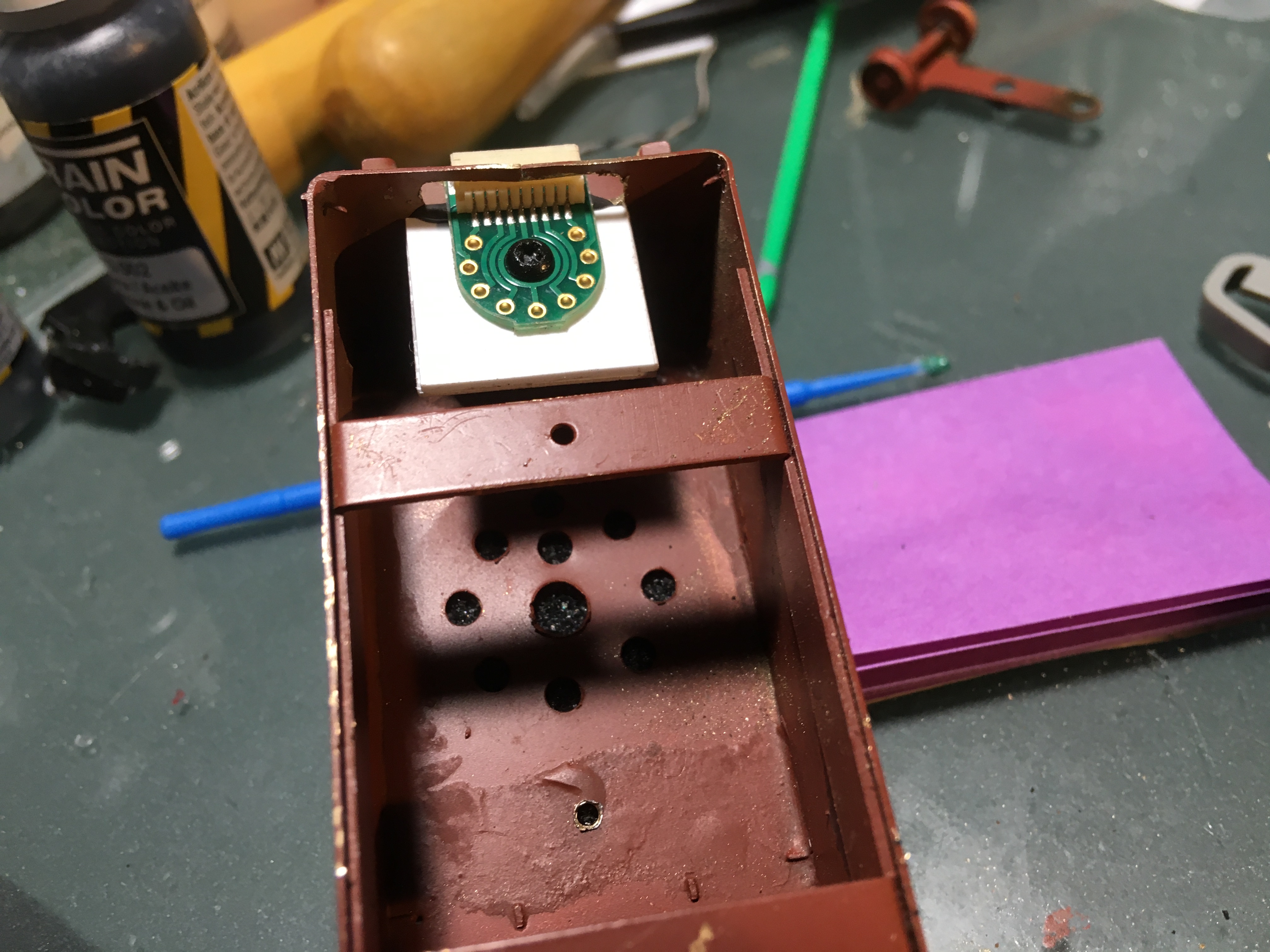
With all of the DCC and sound in the tender, I started to work there. First decision, where to mount the speaker. The coal bunker is already a flat piece, ready for a shallow coal load so no need create a false bottom as recommended by Soundtraxx for a tender speaker install. Soundtraxx has become my decoder of choice, based primarily on local availability and support from my local hobby shop, Pro Custom Hobbies. I had already purchased the latest Tsunami2 Steam2 decoder for my Q-7f, so I diverted its installation to the E-27. I used a large 28mm speaker because I had one on hand and the bigger the better with speakers, for the most part. Using the Soundtrax enclosure for that speaker allowed me to be less concerned about sealing the tender joints to create an air-tight speaker enclosure. The enclosure kit has a mount which I used as a template to drill and tap two 2-56 holes from the top so I could secure it from below. I also drilled some holes for the speaker. As long as it is a sealed unit and securely mounted I don’t need to worry about a gasket for tight mounting or sealing the openings in the tender for quality sound. I used the same setup in my FA-2s and the sound is pretty close to full range and booming.
As brass steam engines often rely on pickup from the tender wheels for one pole and the locomotive for the other pole, stalling is a possible concern. I am adding a Soundtraxx 810140 CurrentKeeper to hopefully help the short model traverse rough spots. It fits neatly into the upper, rear fireman’s side corner of the tender and does not interfere with other parts of the DCC and sound install. It comes with a plug that goes directly into the Soundtraxx decoder, so an easy add. Some high quality 3M double sided tape will secure it to the underside of the tender deck.
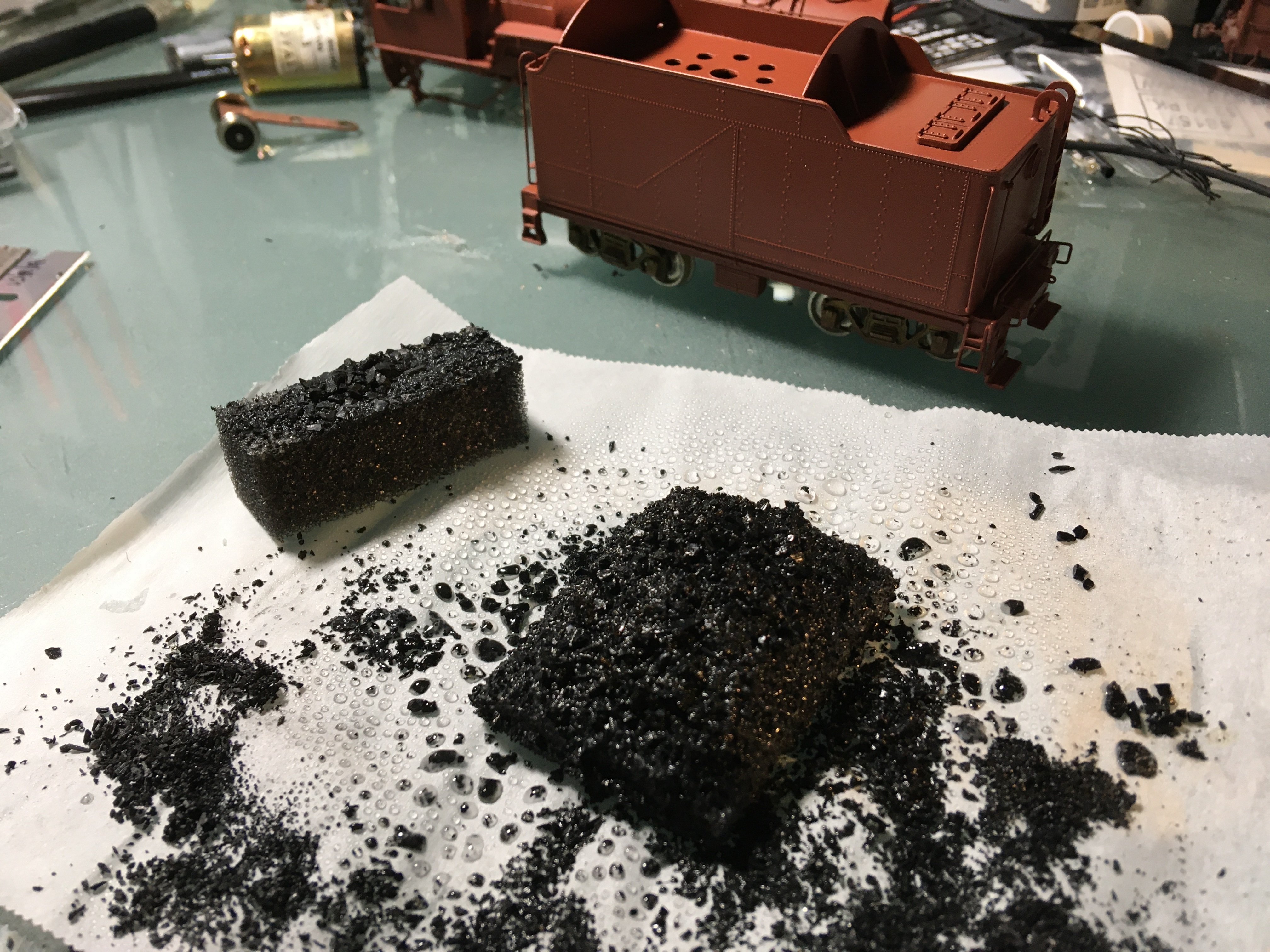
The coal load covers the speaker so it has to be fairly sound transparent. A tried and true is method is black foam. I got a piece from a box and trimmed it fit. It doesn’t look bad plain, but an application of thinned white glue and some Woodland Scenics coal and I have a great looking, sound translucent coal load over the speaker.
Black foam without coal. Black foam with a coal load. The rectangular piece was an experiment to see how the white glue worked on the foam. It does.Soundtraxx DBX-9000 Locomotive-to-Tender Wiring Kit installed on insulated plate and through new opening in front side of tender. I covered this with tape while painting.
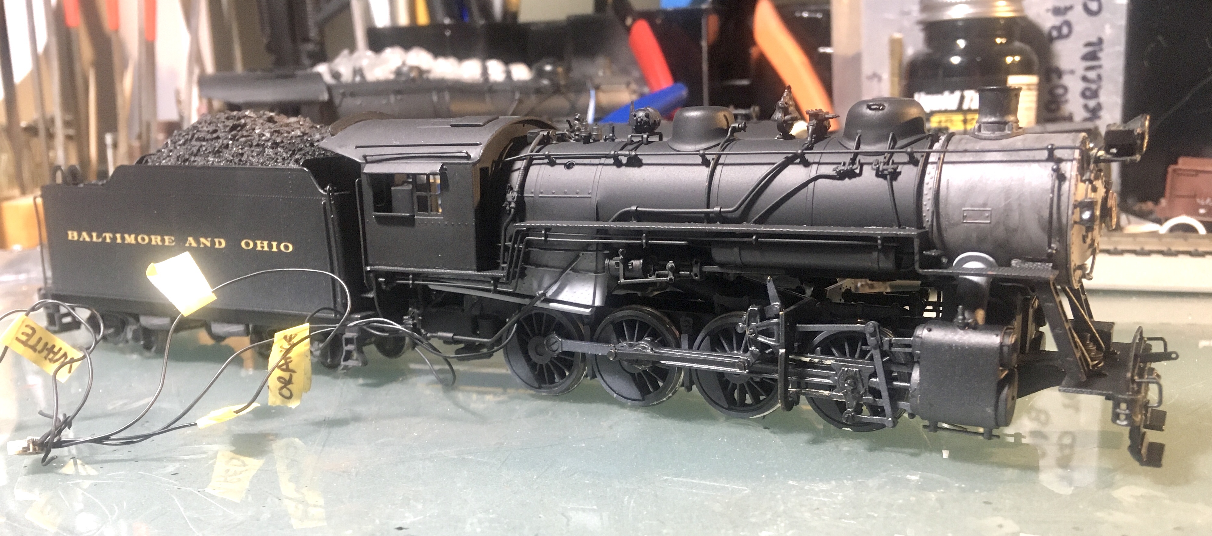
The next step for the tender was a coat of Vallejo Model Air 71.157 Black. I taped off the loco to tender connector and a previously soldered spot on the tender base to keep them paint free for better soldering later. I painted the two pieces separately, along with the trucks.
Next I brush painted some Pledge Floor Finish on the tender sides and rear to be decaled and added decals from Ed Sauers’ excellent set (available from Bill Hanley, email him at wmhanley at verizon dot net). This included the main lettering on the side, engine number on the tender beam, capacity data on the tender rear, along with the tender frame number centered on the lower side of the frame. I chose to do this before adding the DCC parts to allow me to add two coats of Testors DullCote. I wanted the clear layer in place to protect the finish, as I was soldering wires and adding parts to the interior. I also brush painted Vallejo Train Color 73.003 Steel in the tender light opening. This was repeated for the locomotive light.
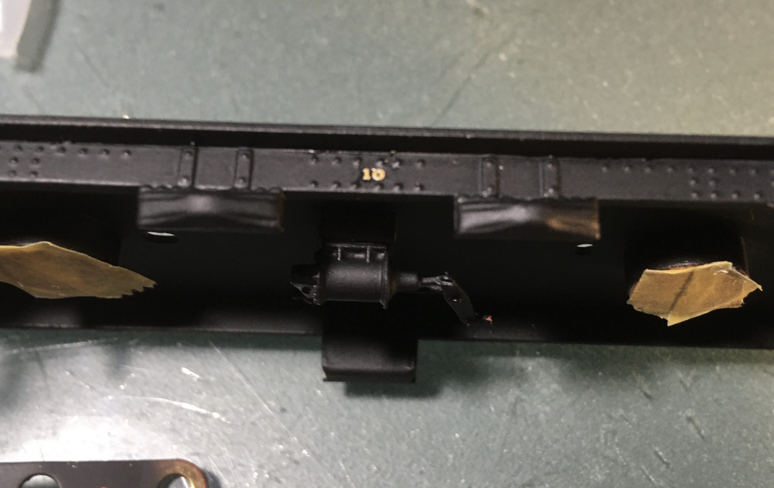
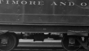
Tender capacity and locomotive number decals on the back side of the tender. As seen on the diagram and in the prototype photo, the tender is identified as a #10. The decal sheet has 2” letters for this and I verified it on a prototype photo, so I added it. Not something I have noticed before.
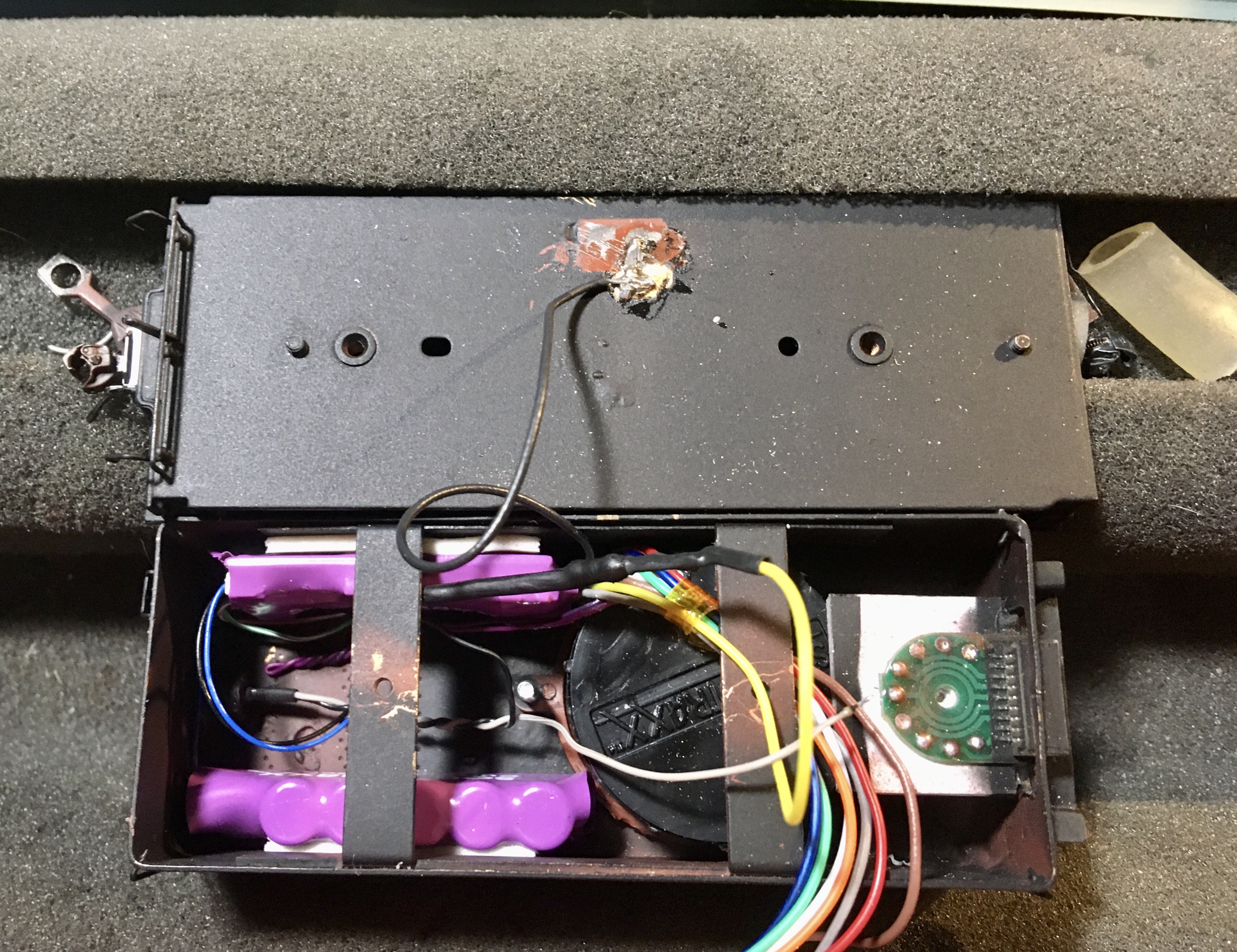
The next big step is putting the electronics in the tender. It is a tight fit as a chose a big speaker, important for excellent sound. I am using a Soundtraxx 810153 28mm (1″) Round Speaker with the 810110 28mm Baffle Kit. In the photo you see the Soundtraxx 810140 Sound CurrentKeeper on the bottom left. It is plugged into the decoder which is opposite, in the top left of the photograph. I first added a micro LED for the rear light with a 1k ohm resister on one leg. I tested it with a 9 volt battery to make sure it is still working after being installed. It has one the black wire which goes from the rear of the tender (left) to the Tsunami 2200 yellow wire which is the rear light negative. The common positive for lights is the blue wire which is T-spliced with the gray rear light LED wire and then connected to the locomotive female side of the connector (Soundtraxx DBX-9000). The black left side track pickup is soldered to the base of the tender.I repeatedly checked the continuity from the wheel treads to the frame to insure good pickup from the track.
Testing the LED lights often is good idea before things are buttoned up. The resistor is soldered in place before the test.
The DBX-9000 female connector is soldered to the wires from the decoder. I marked there location on a diagram and the photograph below that will be stored in the engine’s box. On the connector that is part of the locomotive I labeled the wires with there decoder wire colors to help with final installation. They are all black wires so marking them is important for installation and any future maintenance.
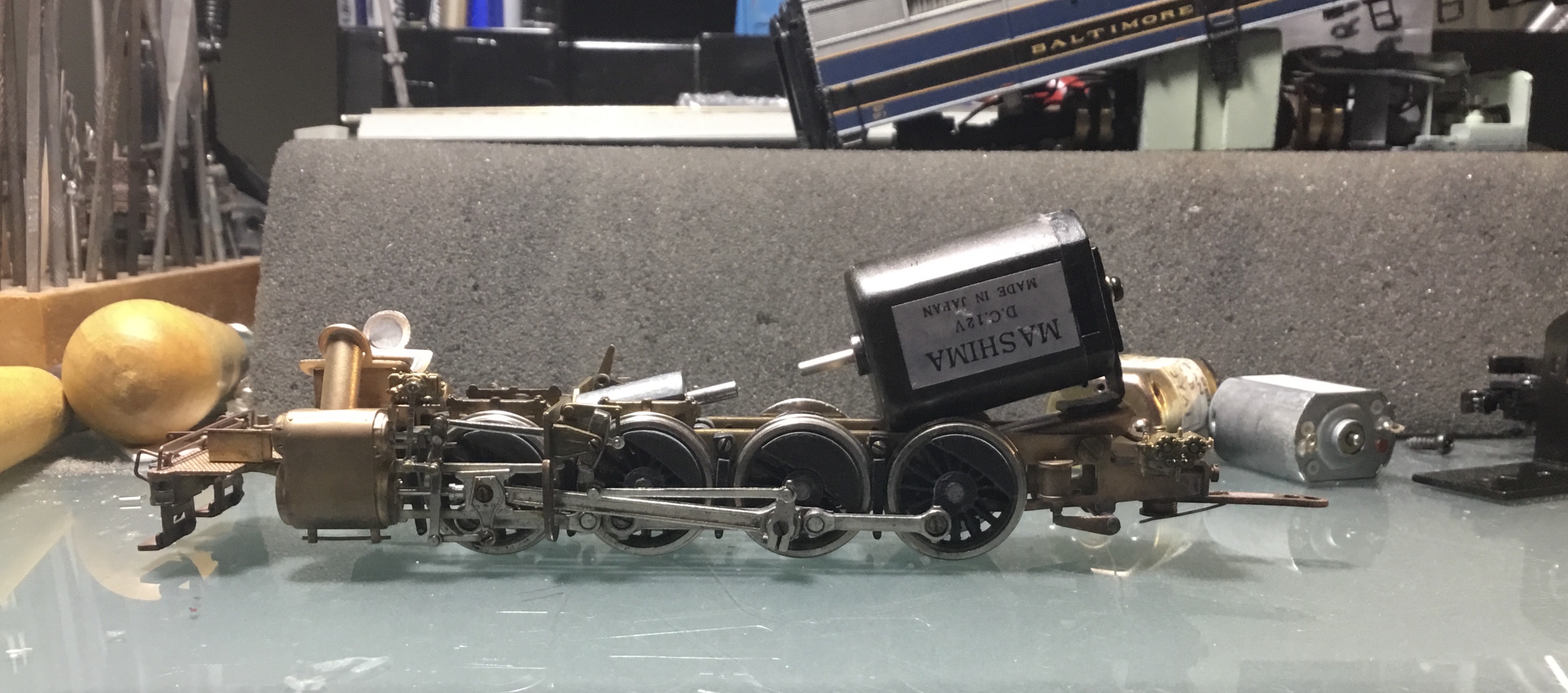
Things are coming together and the mechanism was cleaned with contact cleaner to remove old grease and to make sure there is minimal resistance in the rotating parts. With NWSL on temporary hold for motors, I was very fortunate to have a fellow B&O modeler offer me a Mashima flat can motor from his private stock. He also gave me three inches of thick walled tubing for the motor to gearbox coupling. Thanks Ed.
This mock up look like I am on the right track. The gearbox will change when the driver springs are added and I can adjust the motor mount to match.
The motor had a small mount on it and I was able to add it to the plastic, insulated side of the motor and it lined up well with original gearbox. The negative wire is attached to the bottom of the motor and seen in the photo below. After adding a new 2-56 threaded hole in the original mount between the frame rails the new motor mounted firmly. Capton tape will be added the motor case to insure contact between the case and the frame do not cause a possible short. The tubing was cut to length and holds the gearbox firmly in place in both directions. So far it runs like a dream on the test track with leads connected directly to the motor. I am also constantly checking the continuity of the pick wheels on the locomotive and the tender to insure they are solid when I connect the decoder.
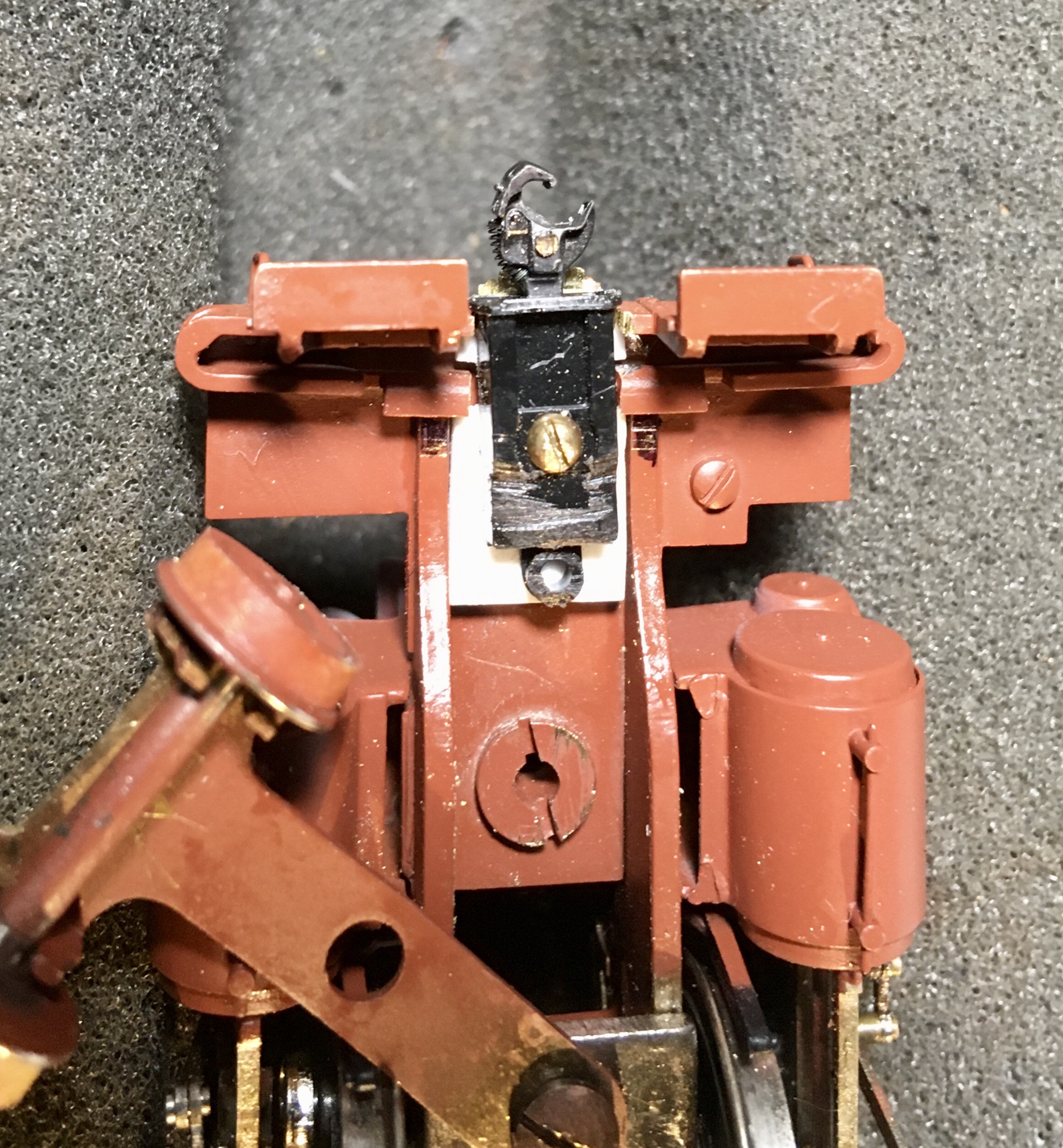
With the most of the electronics in the tender, the connector will have five wires used in the locomotive. I added a rectangular slot in the vertical plate behind the cab (photo below).
Painting and weathering is another comfort zone for me to fallback on when the modeling gets difficult. I wanted to experiment with a well weathered smokebox, so I gave is a shot of Vallejo ModelAir 71.050 light gray paint and then gave it several washes of Tamiya 87131 Black Panel Line Accent Color.
If this works out I will use a similar technique on the firebox . We’ll see how this looks after the boiler gets a coat of black paint .
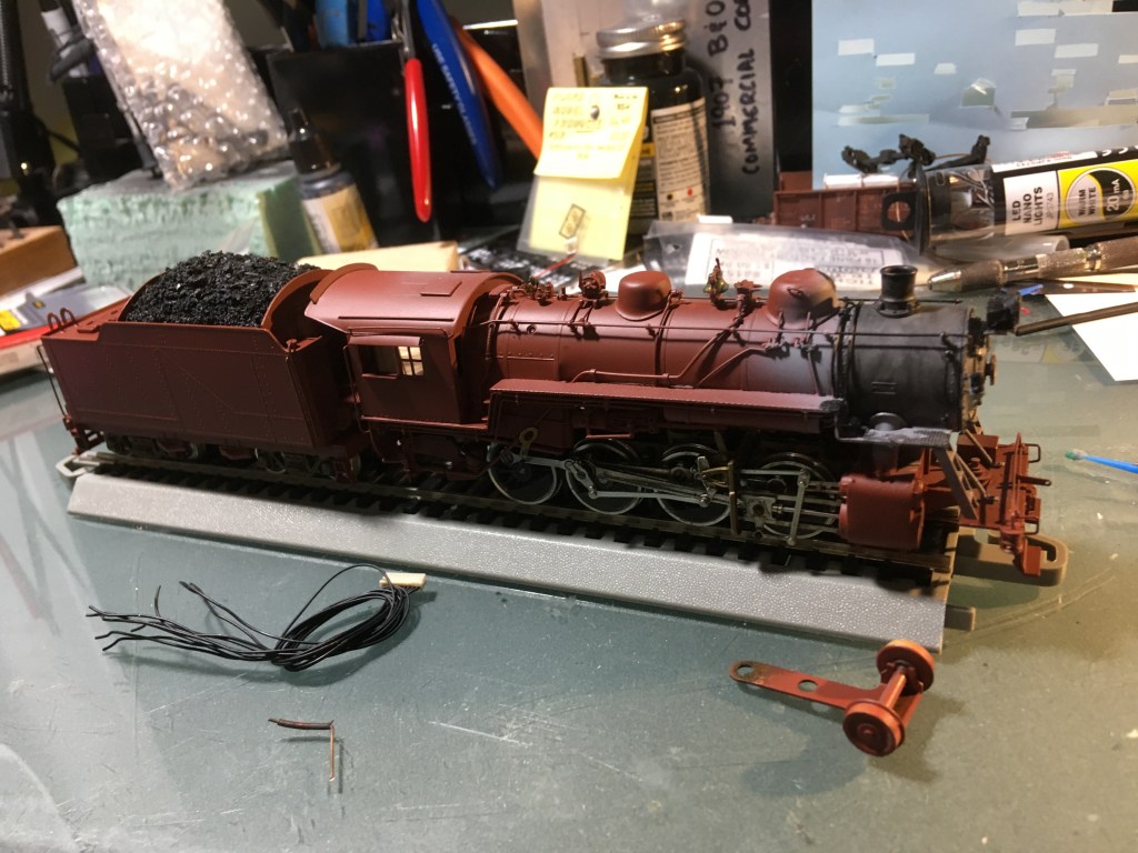
The firebox was painted the same grey and then along with the smokebox taped over with Tamiya thin masking tape. This tape makes a nice edge, sticks well, and it’s thin width helps seal off small areas. I think I cut fifty small pieces to go over and under pipes and railings.
Not sure all the taping was worth it but here is the initial result. I used a fine brush to touch up the pipes with black paint.
Ready to go!
Something I have noticed in black and white photos of steam locomotives compared to color is the finish. In many color photos the whole locomotive looks black, one color, b&w photography seems to catch or show tones of black. Maybe tone isn’t the correct word, but the boiler looks a different color than the cab and tender, I am guessing this is related to temperature of the metal or how heat affects the paint. Either way, I want to see if I can capture this with paint. After spraying the smokebox and firebox with gray to represent the graphite finish on these hot areas, I sprayed the rest of the engine with black. But to finish, I am overspraying the cab to match the rather “cooler” tender with a gloss coat and then Testors dullcote. The boiler, after masking off the cab, will get a gray flat over finish to attempt to capture the variation seen in b&w photos. it may not make a difference, but this a platform for experimentation.
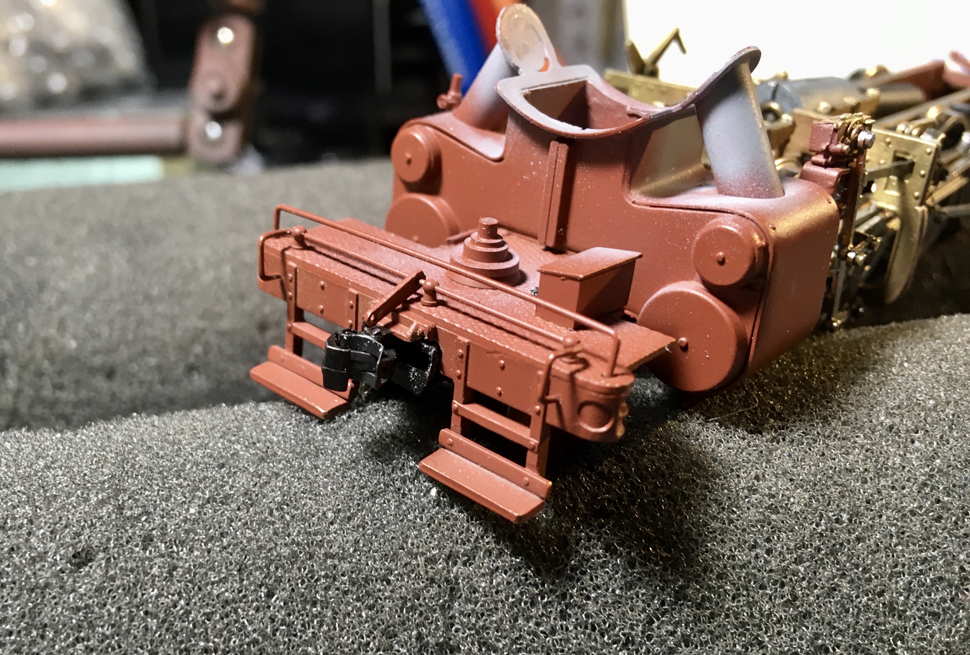
The front coupler on brass locomotives always seems to be a challenge. The dummy coupler was removed from the detailed brass coupler pocket on the pilot beam with some heat from a soldering iron. I used wet paper towels to keep the surrounding surfaces cool while heating up the pin that held it in place. After removal I had a well detailed coupler pocket that I could add a cut-off Kadee coupler by using the same technique as it came with, a shortened shank with a pin through it, marginally functional. I chose to add a full Kadee #178 coupler and pocket instead. I felt it would provide better operation to a locomotive that will be used in switching. Using a cutoff wheel in my Dremel, I trimmed out a wider opening in the pilot beam all the way up the bottom of the pilot deck. This left a little bit of the prototype looking draft gear in place. I shimmed the underside of the pilot deck with styrene to allow me to screw the #178 draft gear in place and provide a mechanically strong connection. I didn’t want to try to drill and tap a blind hole into the pilot deck. The styrene was epoxied in place and tapped for a 1-80 screw to attach the Kadee draft gear.
It is centered, though the photo angle makes it appear otherwise. I had to file the back end of the draft gear to help clear the pilot truck. The pilot truck was also trimmed a little to help with clearance. The top of the original coupler pocket is still in place and adds a little extra detail to the installation. The coupler hits the Kadee gage well within my specs.
Lighting is always something I want add to my locomotive fleet though I have learned the B&O didn’t require the use of a light during daylight operations in 1950. For the tender I used an LED from Woodland Scenics as size wasn’t extremely important as the light is mounted into the tender body. A Details Associates 14 1/2 inch headlight lens is the finishing touch for the rear light. One was used on the headlight also.
Final Tender details included adding a Kadee scale coupler and Hi Tech Details brake hose to the back of the tender.
Weathering is light with an undesrpray of light gray-grime.
Which prototype to follow? One of the reasons I bought this locomotive as a test bed was my experience on John King’s prototype operating layout of the B&O Branchline to Winchester, VA. I wanted to commemorate that great experience. I got to run an E-27 on the local through the layout with the help of an experienced conductor. I have never been interested in layout operations, but this experience changed my perspective. I was also very lucky as the other operators on that day were very experienced, one literally wrote the book, and they were all gracious and encouraging.
I asked John which E-27 could have possibly run on the Old Main Line. He gave me a quick lesson on the E-27 and how many had their cabs shortened thus limiting the prototypes for the model I possessed, unless I wanted to do some major rebuilding. He offered photos of 2712 which had the longer cab. Some other details don’t match, but I am proceeding with this number as it was in Brunswick and might have traveled down the OML, maybe on a work train or for some other plausible reason. Thanks John, this one model that is more than a replica of a former prototype, it is a memory of a great day.
I have written before about my switch to acrylic paints, specifically Vallejo paints for airbrushing. To keep down the mess in the house, I wanted a cheap, lightweight spray booth with lots of light and an exhaust system for the particles and slight odor. I have been airbrushing inside with a cardboard box and using a respirator to catch particles before the entered my body. It had its limitations.
The Old Cardboard Box Solution.
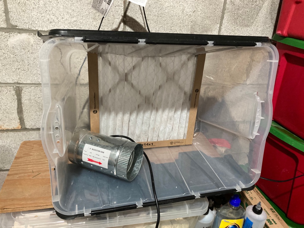
I started with the idea of using a plastic storage crate about the size of my cardboard box. The plastic was hard to work with as it was brittle and my search for an inline exhaust fan didn’t work out. I was hoping the clear plastic could help with lighting inside the booth, be lightweight, and portable for future moves.
The Original Paint Booth in a Storage Crate Idea.
I live on top of a large granite and marble deposit, one of the revenue sources for the NCR that run through this area starting back in the 1830s. These deposits off-gas low level radiation, so my house is fitted with a radon removal system. It is basically a hole in the basement slab with an extraction fan outside of the house to pull the radiation up and away from the house. When I first moved in seven years ago, the exhaust fan on the side of the house wasn’t working, so I found the same fan model and replaced it. Just last month the fan started to vibrate, maybe a bearing was wearing, and it caused a reverberation throughout the house. A new fan was sourced for about $150 and the replacement (a new model number with slight design changes) ended the house-wide vibrations. Then I realized I had a fan that could pull 160+ cfm that works, but with a slight vibration. Paint booth dreams were again alive. And one big advantage is this fan is that it is meant to connect with 4″ PVC pipe and easily adapted to use flexible, metal 4″ dryer hose connections.
The main lesson that I can share from this experience is that lightweight construction is possible on a budget. A little time woodworking with a table saw can provide a strong frame and the walls can be thin and lightweight. Like the walls on the inside of a house, the framing provides the structure and the skin can be weak. Having enjoyed the size of my cardboard box, I used it for a start and created the main structural members from 3/4″x 2″ poplar. You can use another wood, but I was lucky to have access to some hardwood stocks that a friend was willing to share. I created two 18″x !8″ frames for the sides and used half-lap joints with glue, then a light spray to polyurethane to seal the wood. A glued half-lap joint is very strong and provides the main structure for the booth. The width between the two sides was determined by the width of a roll of easel paper. I saw this online, someone used a roll of drawing paper hung at the top, back of their paint booth to allow for a renewable white background for painting and possibly photography. The rolls are available through Amazon and much cheaper at many craft stores for $6, they are used for children’s art easels.
Gluing Half-Lap Joints on Side frames.A Light Coat of Polyurethane on the Side Frames.
For the bottom of the box I used a thin piece of plywood lying around in the garage. It was 1/4″ pine, which helped with keeping the box light. I added a second piece of 1/4″ under the front lip for dimensional stability. My second choice was a piece of 1/2″ birch plywood left over from layout framing. The width was 20″ to allow for the paper roll to fit within the side frames. The depth was set at 22 1/2″ to give me a little lip on the front of the box for paint bottles, cleaning supplies, and the spray-out pot I use to clear my airbrush. The side frames were screwed from the bottom of the plywood base. I skipped glue here in case I want to take it apart or adjust the size. The added a lip also gave a place for the paper roll to be slid under and secured.
The Paper Slides Under the Lip.
I wanted the top to be clear or translucent to allow light to enter the box and possibly add lighting from outside the box. I was leaning toward buying some plexiglas to cover the 20″x 18″ top of the box. I didn’t need a solid piece of plywood like the bottom foundation, so I was thinking of just using some 20″ wide scrap strip to the keep the sides from moving too much with the plastic to fill the space. Once again a scrap piece of material came to mind. I had several 12″x 12″ pieces of glass from former wall decorations that I had saved to use for my modeling bench as replaceable smooth work surfaces. A couple of pieces of the poplar hardwood I received had reliefs cut into them so two 18″ pieces became the top braces, along with another scrap piece for the back edge. I was going to screw the glass in place as the pieces had holes in the corners, but I decided to use two more pieces of the same trim to capture them in place within a frame, a few thin screws helped hold this together and make it removable should the glass become to covered in overspray.
Top Frame and Light Opening.
For lighting I am using a simple metal, portable flood light sitting on top of the glass and two short screws into the cross braces to keep it from moving and stay above the glass. The light fixture is fitted with a 5000k LED floodlight bulb which operates cool to the touch and is the same bulb used over my layout. Do not try this with an incandescent bulb, they are way too hot and a possible fire hazard being in contact with cardboard and finished wood! The 5000k bulb should help with having the paint applied in the booth look the same as it would on the layout.
LED Light Fixture in Place.
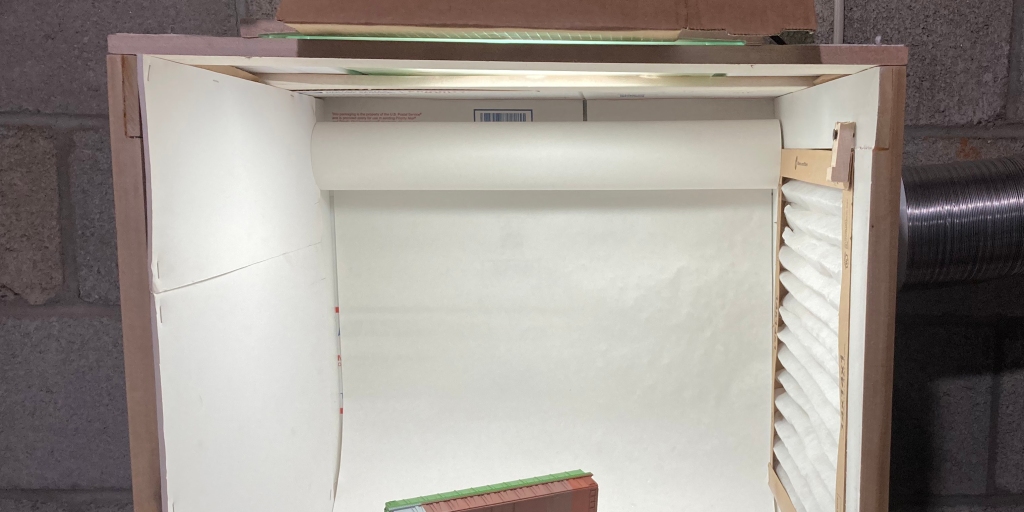
A simple dowel was used to hang the roll snugly between the sides. I mounted it as high and as far back in the box as possible. The roll I bought is 75′ long so I need to remember to buy the same size in a few years as I have seen much longer rolls with larger diameters available. The cardboard used for the back wall is visible.
Adding white cardboard or foam-core is just the covering for the back and the sides, it provides no structure, but keeps the negative pressure pulling air from the front of the booth (where is protects the user) and white allows for better light reflection inside the box and thus more light on the paint subject. It is just stapled in place so that it is easy to replace. We’ll see how this works over time.
The radon fan needed a mount as in its primary use it is attached to braced 4″ PVC pipe with rubber collars on the outside of the house. (insert photo of fan outside house). Here again I took advantage of scrap lumber, this time a 24″x 24″ piece of birch 1/2″ plywood left over from my layout’s modular structure construction. I built a shelf 10″x 10″ to be as wide as the fan and used a jigsaw to cut a 5″ hole in the center to allow the fan body to sit down into the shelf. To mount the shelf to the cinder block wall of my basement I cut a mounting bracket with a dado cut to fit the shelf and then added some angles from the shelf down to the bottom of the mounting bracket. I gave this a light spray of polyurethane to give it some dimensionally stability over time. After attaching the mounting bracket to the wall with three Tapcon concrete screws, I added a couple of drops of acrylic adhesive caulk to attach the fan housing to the bracket and keep it from moving around, while providing a soft mount to keep vibrations to a minimum. I only used a couple of drops of adhesive as I want to be able to cut the fan free should it fail in service.
The Assembled Parts of the Radon Fan Shelf and Mounting Bracket.
Venting the booth outside house is always a challenge. A window can be a great option. I didn’t have this option in the unfinished side of my basement. Then I caught a lucky break that not one in a million modelers gets, I found an unused dryer vent to the outside just seven feet from my intended booth location. It still goes outside and was plugged with expanding foam to keep out small animals. I can’t figure out why it is there, the washer-dryer is fifteen away and there are no nearby plumbing connections to suggest the washer-dryer had been moved at any point. I can’t help you if you are not that fortunate, but I can say the radon fan will push some air as it is sized to move a lot of air two stories up, so a longer run on the exhaust side of the fan is practical. Keep in mind this is only for use with non-flammable solvent paints and finishes, don’t try this with flammable solvent based paints!!! If it doesn’t clean up with water, I don’t use it.
A Fortunate Dryer Vent.
This is a design-build project, so I had a general sketch or two in place and set out to build it to meet the design intent with the materials on hand, adjusting as needed. And I am writing this blog as I am building it, so one of the last details to complete was how to connect the duct work to the side of the box. In the original plastic storage crate design I was going to use a 14″x 14″ filter in front of the fan connection at the back. I realized a side mount fan would be better for my new box design and allow the booth to sit closer to the wall and more out of the way. I knew this wasn’t a good a design to get the best laminar flow across the face of the paint booth, but with 160 cfm pulling through the fan, I was going to exchange all of the air in the box about once every two seconds. Adequate air flow shouldn’t be a problem. The plan was to put a 4″ coupling for flex duct on the top edge, near the back of the side nearest the fan and use some type of filter to protect the fan from paint particles. So far I have only invested time, as all the materials were on hand. I grabbed the 14″x 14″ inch furnace filter to see how I could attach it to a side frame or maybe consider something else. Serendipity struck again and the filter fits perfectly into the popular side frame opening. It was a press fit! I would like to say that was planned, but it was per luck. With the fan pulling through one corner of the filter, I actually think I can get four times the filter life as I will rotate it periodically to put a fresh corner of the filter closest to the fan intake. So next I attached a coupling connection to a 5″x 5″ piece of the 1/4″ plywood with a 4″ hole and…
Furnace Filter Press Fits into Right Side Frame
The finished box, now a paint booth, needed to be attached to the wall and/or held up on legs. I wanted the booth at layout height so I was painting models at the height they would be viewed. I decided to use some plastic shelves from Lowes that are 18″ wide. I attached them to the wall with 1-1/2″ conduit clips to keep it in place. It was a little top heavy. The $20 shelves gave me a place for paint and thinners. A nice bonus.
I connected the flex dryer hose to the connector and hit a few gaps with duct tape for some and caulk for permanent connections. I may add a piece of plexiglas across top front to increase air movement through the box. It pull the fumes away, but you can never have too much ventilation.
Duct Connection, Cardboard Sides, and Conduit Straps Holding it All in Place.
This was a fun project and added a little professional touch to my modeling. It doesn’t hurt to have nice tools and this one was low cost. Model on ya’ll.
The turnout shown in the back has only been treated with Micro Engineering (ME) Rail Weathering Solution, no paint has been applied. The foreground track is ME Weathered Code 83. The match is pretty good and I didn’t have to worry about cleaning off paint.
So I mentioned I spent some time as a Trackman on the B&O. That experience taught me that turnout ties were not often replaced at the same time as regular ties. Those standard ties were much more available for track gangs to replace and of course there are so many more compared to switch ties.
A prototype photograph from my modeling era about 2000 yards west from the spot modeled in the previous layout photo. The first two tracks are the mainline looking west to Point of Rocks. (B&ORRHS Photograph)
I mention this as there are some prototype reasons why switch ties look different from all the rest as far as weathering and condition. At least on a well maintained line. It is not unusual for the longer switch ties to all be of similar age, while the standard ties around them may vary in age. The standard ties are replaced as needed, while a turnout would be repaired more likely as a unit with most or all ties being replaced. This is a factor in weathering for a model railroad. The rail on the other hand may be laid at a different times, but it’s weathering for modeling purposes is more uniform as it lasts much, much longer than a wood tie. Although turnout rail is replaced as a unit usually also, the intervals are just much longer. A Track Foreman or Track Supervisor will gauge turnouts and oversee construction, a lowly Trackman can gauge other track and spike it. Speaking from experience.
My modeling project is using Micro Engineering products and the track I bought is pre-weathered, though the turnouts do not come pre-weathered. Based on my earlier statements, I believe I should weather the rail similar to most of the rail in proximity, while the ties can be less uniform, for good reason.
One way to weather rail is to paint, another option is to use a chemical “blackening solution”. I was satisfied with several applications of Micro Engineering (ME) Rail Weathering Solution #49-103 as it turned the turnout rails a dark shade and matches the pre-weathered rail ME offers. Older rail, before the advent of roller bearings on freight cars, weathered a dark, dark gray stained by the grease from wheel bearings. Rail in more modern times often has a hint of surface rust and brake shoe dust that makes it appear a lighter, more orange color. Except maybe near rail lubricators that keep it a more dark gray color.
The closer turnout has several applications of ME Rail Weathering Solution while the background turnout is straight from the package. The application is brush on.
If you zoom in on the layout photo (I did that below) at the top of the post you can see that I have added joint bars and cuts in the track at prototypical distances on the rails. I still need to add a little chalk weathering and finish the ballast details, but the track work is coming together. Its a detail that we often pass over and getting it to match your prototype can help complete the scene.
If you look close you can see the joint bars on each rail. I didn’t add bond wires to the joints.
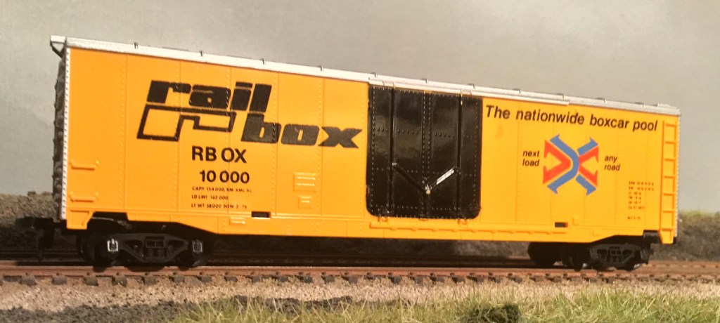
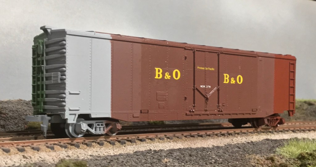
The final results of my techniques for adding paint, decals, and a flat finish to a scrap-box boxcar.
With “Stay at Home” public health orders in place across the United States, it seems many are finding extra time and a renewed need for their hobbies. I am no exception and the time in the evening to escape work tasks gives me a needed change of pace and time away from my kitchen table, now work station. Completing a few projects has been fun, though one painting misstep with Acrylic Floor Finish added some frustration and gave me a reason to consider practicing my techniques and possibly narrowing them down to one basic process and deciding which products I like to work with the most.
For me, the first and most important step in developing preferred painting and decaling techniques was to consider a new airbrush. I had been using a single action Badger Model 200 with siphon feed for years. I did not enjoy it, I could not seem to get fine paint control (also a function of using various paint brands and types) and it took so much paint to fill the jar up to siphon hose, clean up took as long as actual painting time. On and off I subscribe to TrainMasters TV, an online model train video series, and one of the first segments I watched was on airbrushing by a representative of Iwata airbrushes. I loved the fact that by using Vallejo paints and a gravity fed double action tool, the expert on the screen was bale to quickly and precisely paint models and cleanup the brush. Those were the things I wasn’t able to do with my current Badger setup. This is not a knock on Badger, it was the whole system that got me where I wanted to go and I am sure other brands could do that also. I believe the key was the double action for control (takes a little practice), easy cleanup and consistent paint, and the use techniques shown in the video.
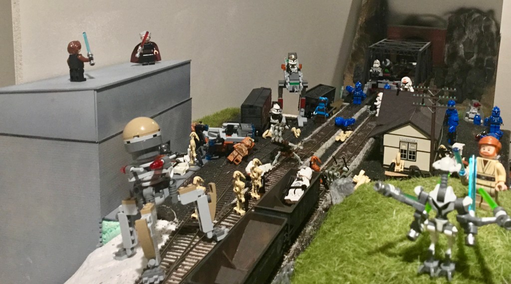
With my son home, part of the layout has been diverted to a Clone Wars battleground. Hoping the Death Star doesn’t wipe out this entire planet.
I ended up purchasing an Iwata Eclipse Hp-Cs Value Set with Hose, then quickly purchased a Iwata-Medea Universal Spray Out Pot and large container of Iwata-Medea Airbrush Cleaner for easy clean up. Watching the video will show the techniques for using all of these much better than I can explain here.
The consistent paint turned out to be the Vallejo Model Air series, they are thinned for airbrushing and available in a wide variety of colors, though not mainly labeled for railroad colors. This is a big drawback, but I decided to tackle it by starting with the Vallejo Steam Engine Weathering Set I found on Amazon and then add colors available on Amazon and eBay as they were not found local to me. Their line of Model Color paints are also a good and only have to be thinned to the consistency of the Model Air paints to produce the same results. I use Vallejo airbrush thinner for this. An excellent source for additional information about spraying acrylics and color matching with Vallejo paints is available at this link, The Model Railroad Hobbyist’s Guide to Acrylic Painting… in a post-Floquil World. This was written and published by the folks at Model Railroad Hobbyist with the support of Testors.
UPDATE: An excellent source for Vallejo paints, which are not always easy to find, is fellow model railroader, George Hollwedel. He is quick, cheap, and again, is a model railroader. Send him an email proto.nscale at yahoo.com and ask him how quickly he can get you the colors you want.
UPDATE: Sometimes a desired color does not come in the Model Air series, or a Vallejo Model Color (meant for brush painting) is the best option. I have adopted a thinner for Model Color paints I found on YouTube at https://www.youtube.com/watch?v=OYyfKPouFCQ. The author suggests using a thinner mixture consisting of 8 to 10 drops of Vallejo 70.957 Retarder Medium (slows drying time) in a Vallejo 18 ml dropper bottle with the remainder of the bottle filled with approximately 30% Vallejo Thinner and 70% Vallejo Flow Improver (thins and reduces surface tension for airbrush use). To airbrush a Vallejo Model Color paint, add four parts of the mixture to one drop of paint. This mixture also aids in brush painting Model Color paints at a one to one ratio.
I have also started my own system for color matching after ordering several Vallejo brown colors that could be used on steam era freight cars. I took a piece of scrap styrene and drew lines on it to allow space for a paint sample along with manufacturer and stock number information. I had done something similar years ago with a few PollyScale and Floquil paints that I could use for comparison with the new colors. The one thing I would do differently if starting over is to have a larger paint sample space, maybe a square inch, and use an airbrush to paint the sample. A few other modelers are using Vallejo paints, and in online forums, I have heard that Model Air Rust 71.080 is a good match for early Santa Fe Brown, and Model Air German Red Brown 71.271 is a good match for early PRR FCC.
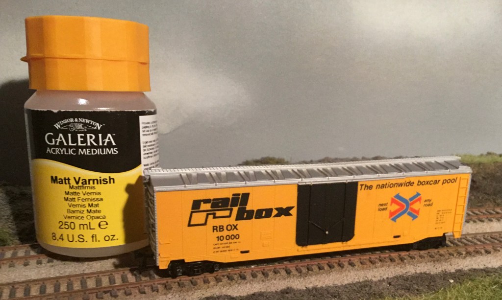
This article started when I was looking a “better” flat finish. I have used Testors DullCote for probably 40 years and have almost always had great results. The few times the results were less than stellar are probably user error. A recent online forum post led me to try Winsor & Newton Galeria Matt Varnish, which I found on Amazon. Sorry I can’t find the original post in order to give credit to the person who shared the information. The 8.4 fluid ounce container was around $12.00 which makes it considerably cheaper than DullCote.
The first trial was on a boxcar from the scrap box that had a very shiny finish. The black door in the photo below show the reflection from a light several feet away. Using my Iwata airbrush I put a little bit in the paint cup without thinning. It was fairly thick but sprayed easily at 25psi and dried fairly quickly. You could see it dry as the gloss disappeared and the best part of the product is water cleanup. I sprayed warm water through the brush into the spray out pot several times and then final washed it, as I always do, with Iwata-Medea Airbrush Cleaner. I did so quickly as I wasn’t sure what could be left behind. Subsequent uses of the airbrush haven’t revealed any residue causing problems.
After it was dry for at least 24 hours, I wanted to see how weathering techniques might work on this finish. In the third picture you can see I applied some Tamiya Dark Gray pinwash (they call it Accent Line Accent Color) to the grabs, ladder, and lower sill and pan pastels to various places on the far end. I wasn’t trying to achieve any particular effect just determine compatibility. The application and results did not differ from what I am used to with DullCote finished models, I see that as a plus. This will be my future dull finish product.
Original high gloss finish as found in scrap box.
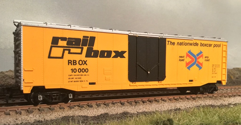
Very dull finish after one coat of Galeria Matt Varnish (same lighting as photo above)
I waited 24 hours and added some weathering to test compatibility.
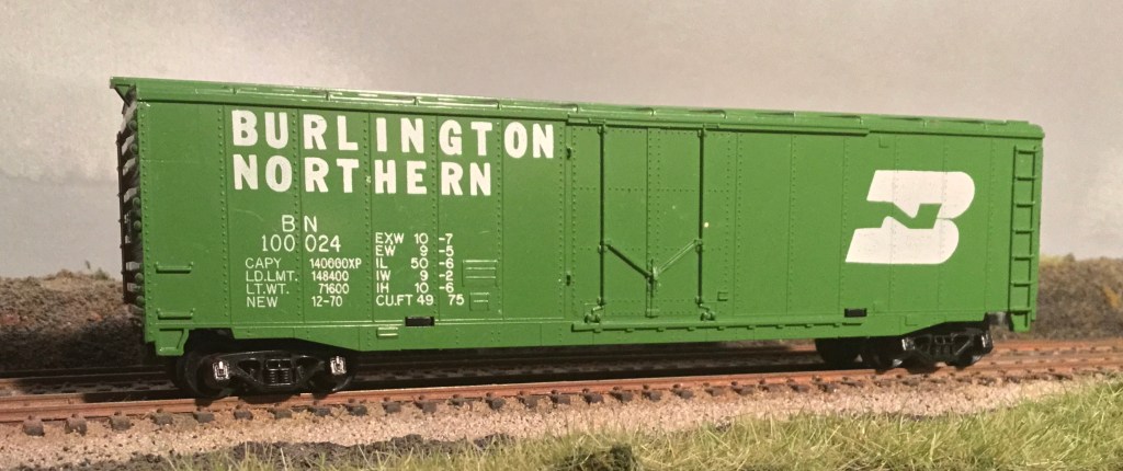
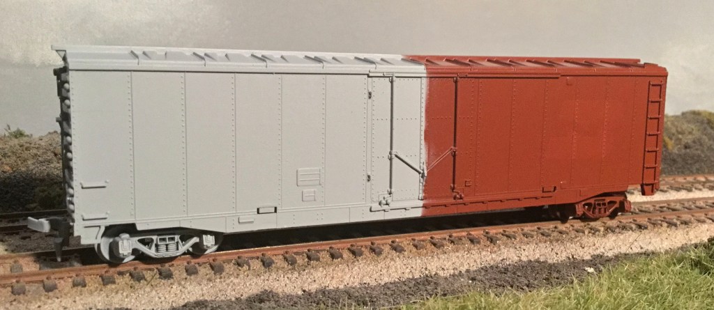
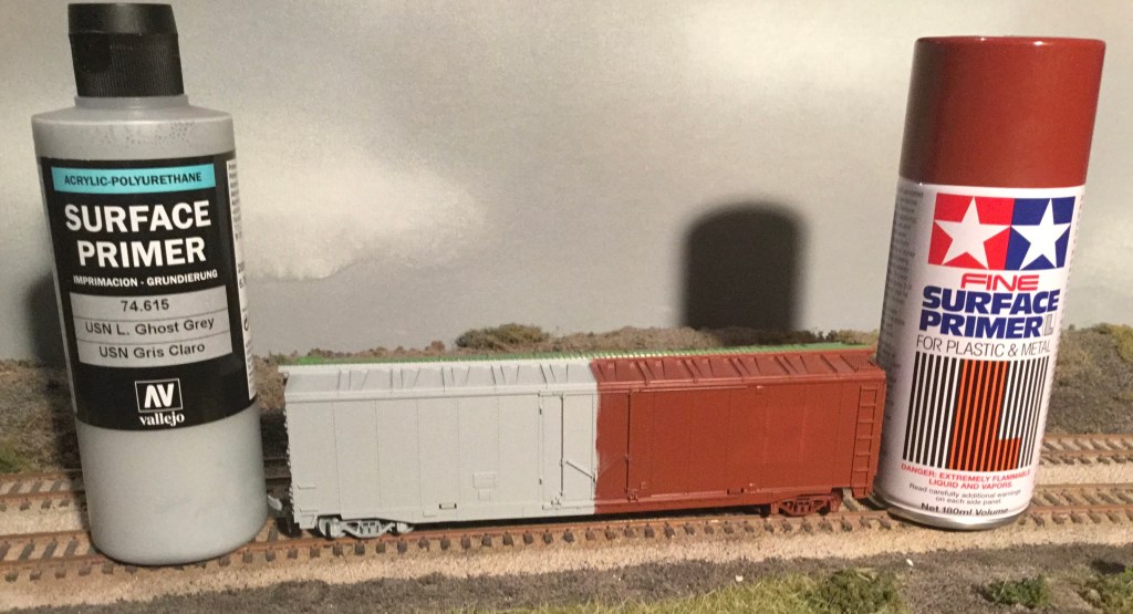
As I stated at the beginning of this blog, I haven’t thoroughly tested my techniques from start to finish, so I decided to give it a go with another shiny boxcar from the scrap box. I left the original finish intact and sprayed half the car with the primer I have been using recently, Tamiya Oxide Red Fine Surface Primer and the other half with a product I have been wanting to try, Vallejo USN Light Ghost Grey Surface Primer. The grey was not thinned and cleaned up with my standard procedure of Iwata-Medea Airbrush Cleaner and the spray out pot. The coverage was better, cleanup almost as easy as the spray can, and the cost significantly less, so I think most future projects will use the Vallejo product. For brass painting, I will probably still use the Tamiya product line for what I feel is better adhesion to the metal.
The original finish.
A light coat of each primer was applied to each side. The right side showed a little bleed through of the original white BN logo.
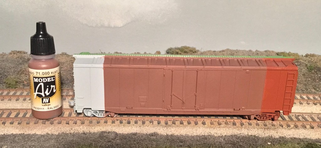
The next step was adding a coat of Vallejo Model Air Rust 71.080, a good freight car brown color. I roughly masked off the ends to keep a little primer showing and gave the model a thin coating sprayed at 25 psi. The results of both ends seem about the same.
Coverage and color of over both primers appears to the be about the same.
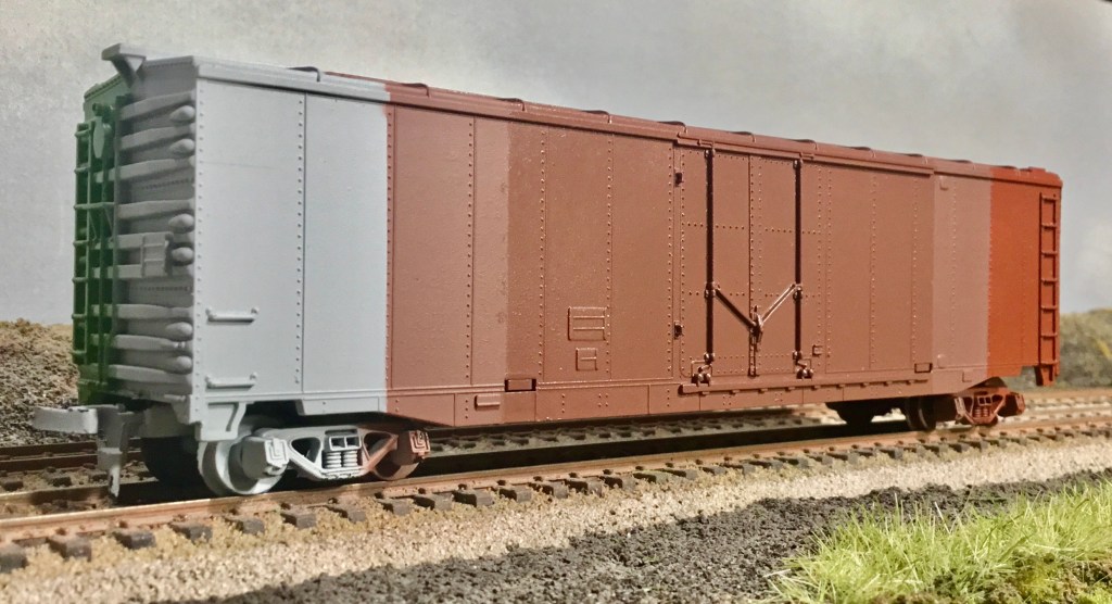
After 48 hours of dry time, the next step will be a coat of “Future” acrylic floor finish to add a glossy, smooth surface for decaling. With so many great reviews online about this product, I really want to master its use. I have used it successfully with a brush on small projects like replacing a reweigh date or adding chalk marks, but I have not done so well on larger surfaces or with an airbrush. I got the best finish on the car pictured when I dropped the air pressure to 20 psi and kept the brush back about six inches. Again, a rough masking job shows the progression of steps from the original green. As an aside, I was painting some blank decal stock green to use on B&O caboose window sashes and found that Vallejo Game Air Sick Green 72.729 is a close match to the BN Green on the original model. The second photo below shows a patch I sprayed with the Sick Green.
Acrylic Floor Finish applied to the center section.
The Sick Green patch is to the right of the door, lower half of the car.
Time for some decals. Part of what started this search for a better process was the use of some very old decals on the recently gloss sprayed caboose I was working on. They disintegrated when I put them on the model, even before adding setting solution. This gave me a chance to learn about Microscale Liquid Decal Film. I used some decals from the same sheet for this project and gave them two coats of decal film. One coat didn’t seem to be enough to hold the decals together. I placed them over rivets and ribs to make it a bigger challenge. My go to has always been Walthers Solvaset so that what I went with. I ordered some Microscale Microset to try for this experiment but it didn’t arrive in time. My Solvaset technique is the lay the decal into a puddle of the distilled water I used to soak the decal and then wick up the water with the edge of a paper towel. Then I immediately apply Solvaset lightly around the edges the decal and let it wick under the decal. If there is too much and it begins to puddle I wick it off the model. I never touch the decal when the Solvaset is wet and I usually keep the model lying flat. I repeat several times over the course of a few hours and watch everything blend into the rivets and seams to know when to say when.
These decals all came from sheets that disintegrated in water and these were treated wtih Liquid Decal Film. I could probably get the film to disappear with some more setting solution but I wanted to see how the matt varnish covered.
I trimmed the decals to allow plenty of clear film to test my techniques and only put on three applications of Solvaset. The decals snuggled nicely on the seams and rivets.
And a final coat of Matt Varnish to seal the deal. Again, I sprayed at 25psi, straight from the container, and covered the surface with just enough to get a solid gloss shine before it dries. It flashes off very quickly and cleans up with water.
The Galeria Matt Varnish covered the decal film well and allowed it to blend very well. I am happy with the results. I left a thin strip of the gloss finish for comparison.
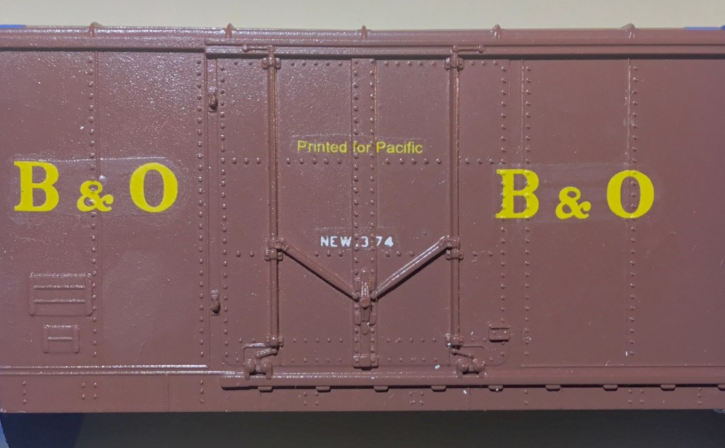
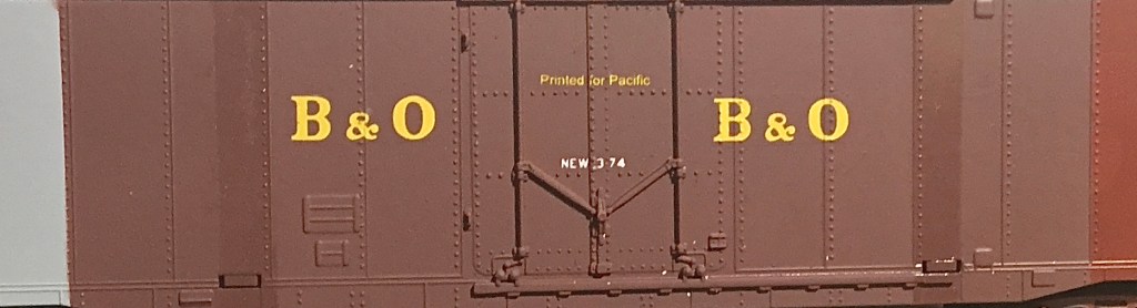
I am impressed with the ability of both clear finishes to lay down a thin coat and allow the rivets to show through the decal. The B on the right was placed on a row of rivets to test this and I think it passed.
This adventure started when I wanted to test a new matt spray finish and it has sold me on that product. Dullcote was becoming expensive and sometimes unreliable because of the spray can nozzles. Now I am more comfortable with the acrylic floor finish and feel like I have a total finishing system that is repeatable and easy to airbrush. Time to finish the caboose I was working on. Stay safe!