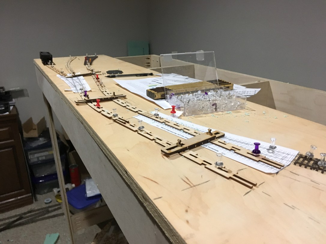
The down side to not having a scale drawing for track design is that things don’t fit as they do on a free hand sketch. Turnouts eat up a lot more space than imagined and transitions have to be more gradual. I took my sketches and started some finer scale drawings, but I found that laying out the track and eyeballing straights and transitions led to better track flow and a more natural look as the trains ran down the line.
I put a long 8’x 2′ – 3/4″ sheet of birch plywood on my layout structure and started playing with the design. I am using #6 Code 83 Micro Engineering turnouts as much as possible, their weathered Code 83 flex track, and their bridge track. I bought several turnouts and also printed templates from their website to assist in the exercise.
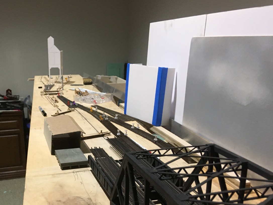
Some Fast Tracks Sweep Sticks in various radii (with 2 1/4″ center radii differences), push pins, and some mock-ups of major structures helped me see the potential and make decisions about distances. Things got compressed more than desired and some things had to be left out. But I needed to visualize the layout in full size with a backdrop, turnouts, freight cars, and locomotives to feel comfortable with my decisions.
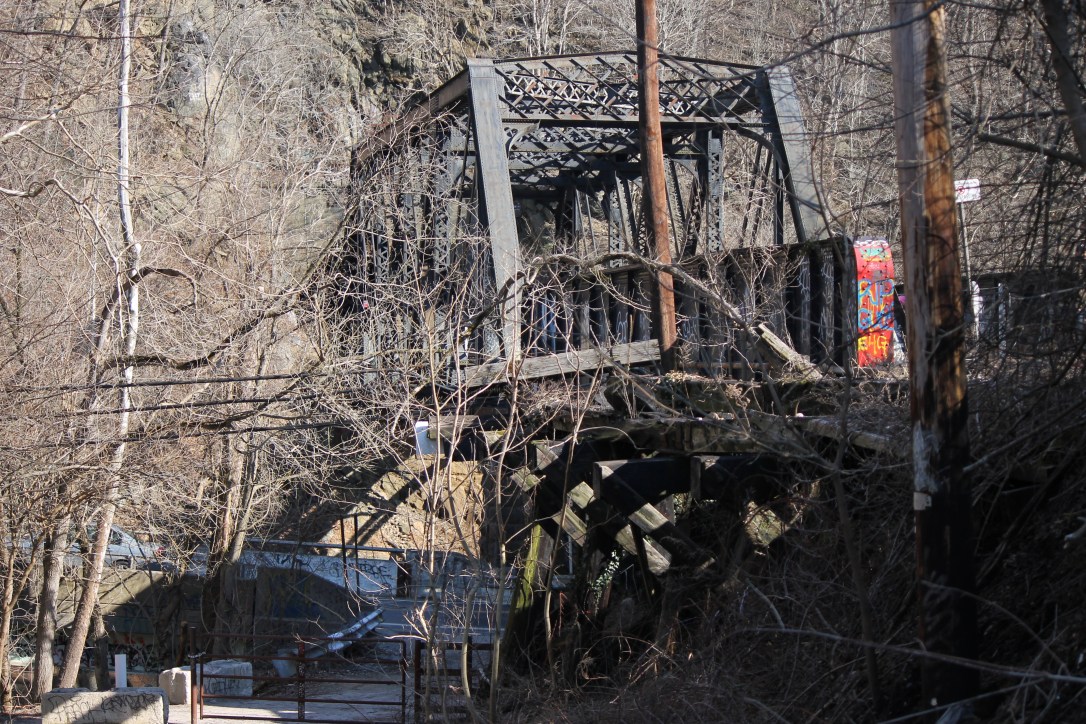
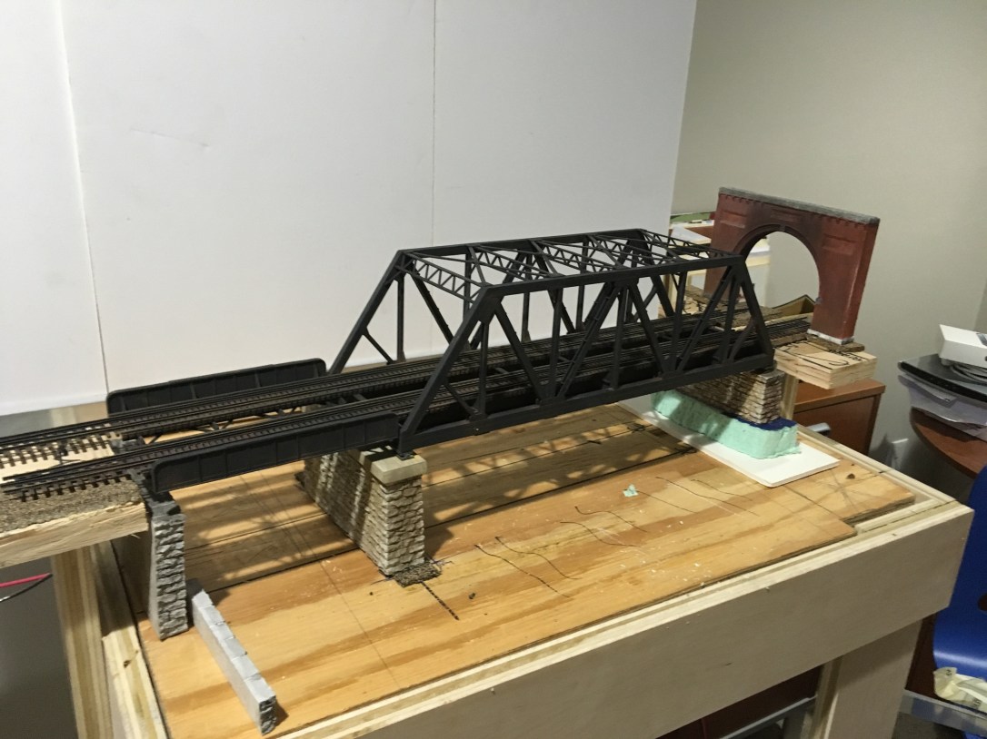
A signature feature of Ilchester is the two bridges that cross the Patapsco River and Ilchester Road just as the roadbed emerges from a tunnel. The line used to follow the river, but a realignment changed that with the addition of the tunnel in 1903. The quick mock up of a concrete coaling tower is the center point for the next location after Ilchester, known as Lees. The tower was added during WWII to help through trains avoid congestion in Baltimore as they headed further east on the B&O. (More on that later.)
The next step was to use the Cookie-Cutter method and trim down the large 1/4 sheet of plywood to just follow the roadbed. For the bridge area, I tried something unusual to make sure I had the right height on both sides of the bridge. I cut a hole in the plywood to fit the bridge and left small supports on either side to make sure the two sides of the gap were in perfect alignment. The track was already glued to the bridge with Pliobond. I fastened the subroadbed to the risers before fully cutting the subroadbed in two.
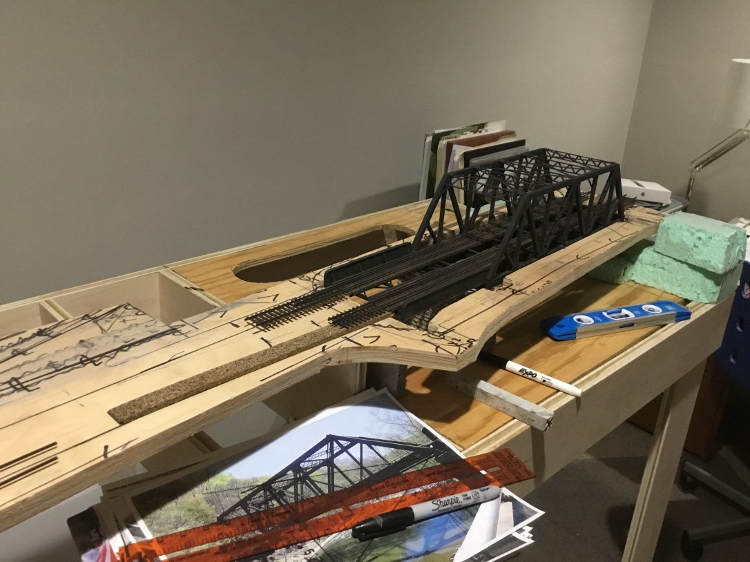
The bridge alignment was a big unknown for me, thus the measures to keep the plywood subroadbed whole before fastening it to the risers. It worked out well and the only thing left was to shim up the supports and add feet for the smaller bridge. The odd shapes of the support columns and the extreme gap for the through girder bridge actually mirror the prototype.
The next operation is to start adding some cork roadbed and track. Let me thanks the many members of the Proto-Layouts@groups.io https://groups.io/g/Proto-Layouts for their insights into the next steps.
I have a sketch of the trackplan beyond the first two modules, but I want to get track halfway through the second module before I start to finalize the design. The Tunnel Portal (a commercial casting that follows the B&O plans for this era portal) leads east to Baltimore and will eventually be moved against the wall leading into the unfinished basement and staging. I may add a temporary track to allow me to run one train in each direction and try operations.

