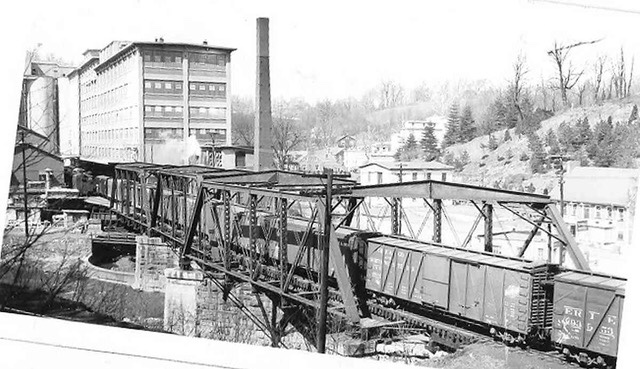
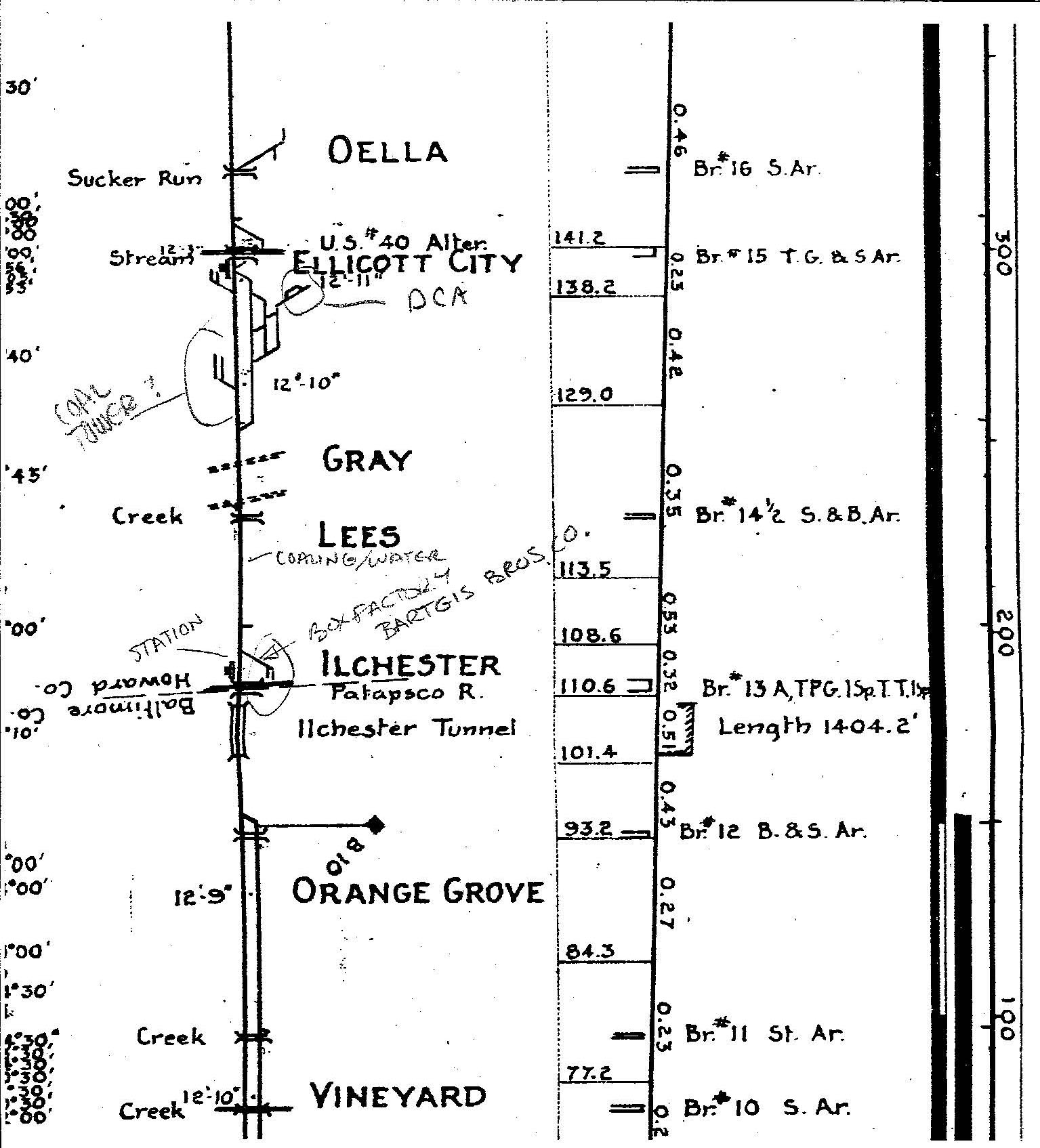
I’ve been working on my layout and not too much of what I have worked on is ready to share. I also realized I have not posted a new blog in many months. Several projects are moving along, new track has been laid to Sykesvile and I have added a crossover west of the Ilchester. The one big project that has consumed my time and required focus is the large joint structure of the Doughnut Corporation of America (DCA) and Continental Milling Company. They were a big customer for the local freight, called the Peddler, on the B&O. The plant is railroad west of Ilchester and just east of Ellicott City’s station.
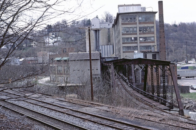
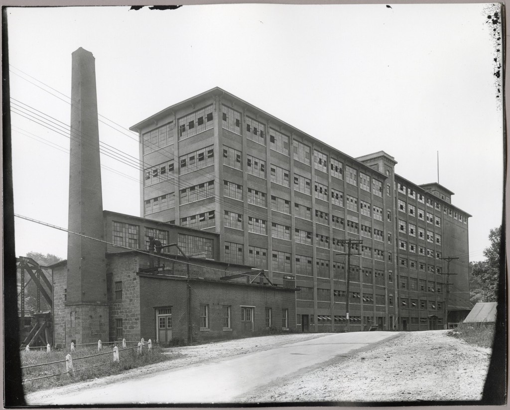
If you’ve been to the area you would recognize the huge structure near Ellicott City as you drive west into the old part of town on Frederick Road. According to a B&O Officers’ Special Train report published in 1953, they received 223 carloads in and 300 carloads out in September. This included boxcars of grain for milling into doughnut mix, parts to make doughnut machines, possibly sugar, and packaging for both products. Continental Milling likely shipped out milling byproducts like bran and middling. At this point the plant was running 20 hours a day. The local Peddler serving the plant ran six days a week, so they would be spotting approximately 10 loaded cars a day, plus empties to be filled and taking out 13 carloads. In this era they would all likely be boxcars. It is possible that an extra train might be dispatched on Sundays or other days to switch cars for the plant. They were a favorite railroad customer for other reasons. According to an account by John Hankey in the July, 2007 issue of Trains:
On my old Baltimore and Ohio division, doughnuts were a form of currency. One of the customers milled flour and manufactured doughnut making machinery which it shipped nationwide. it was a busy operation and it depended on getting cars of grain in a timely manner. For many years, every railroad office between the “doughnut factory” and Camden Station was well supplied with fresh doughnuts. And the railroad would go out it’s way to make sure that this particular customer got the cars it needed, when it needed them.
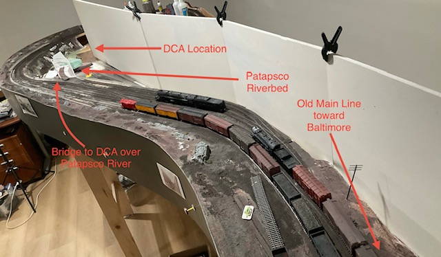
The factory is on the north bank of the Patapsco River and the Old Main Line is on the south bank at this point. The plant is east of Ellicott City, the B&O’s first terminus of its original line west and home to one of the oldest passenger stations in the United States. To serve the plant and what was called the Patapsco Branch, a bridge was constructed across the river, though it was rather lightweight. B&O bridge loading information from the 1950s indicates that Mikado steam locomotives like the B&O class Q-3, Q-4, and Q-7f could use the bridge. In later times, most diesels required idler cars to switch the plant. Those steam engine types were used on the local freight in the 1950s. The plant was served with its own small yard until rail service ended to the plant.
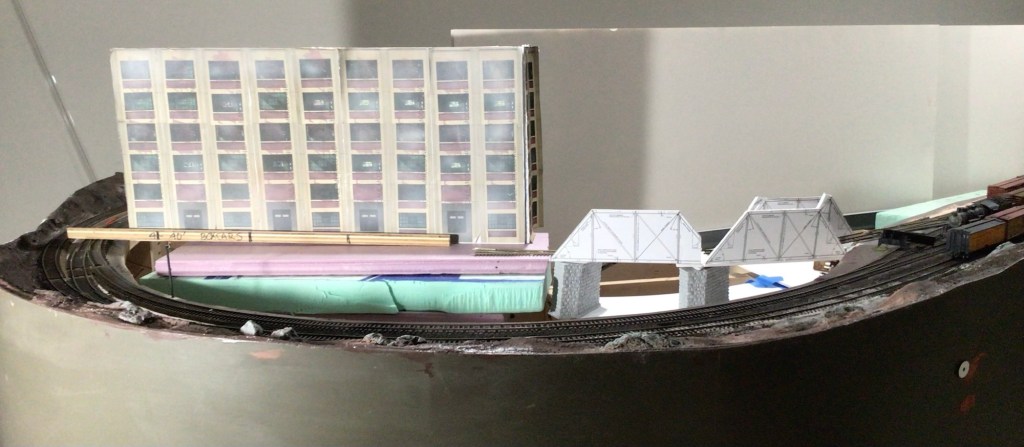
and Central Valley bridge parts glued to foam core.
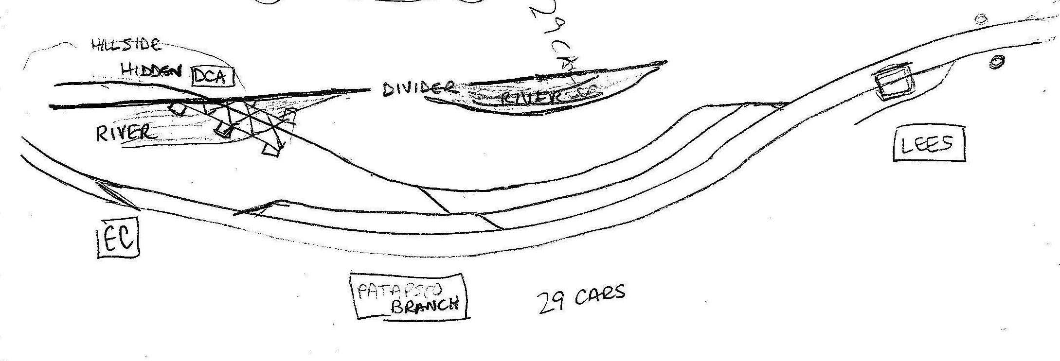
Before I could finalize the model track layout for the module, I had to see how a compressed version of the main DCA building could fit on the layout along with a bridge over the Patapsco River. A mock-up structure was needed and I found a product from ITLA that might work for modeling. They offer templates for planning at https://itlascalemodels.com/collections/building-kits/products/ho-scale-industrial-wall-modules. The mock-up helped and eventually allowed me to change my sketch of the track plan. The option seen below showed the easy solution of putting the bridge in the foreground and the DCA)plant behind the backdrop as just a photo backdrop with nothing to build but a bridge into the backdrop. Some friends talked me out of this and assured me I could have more fun operating the layout with the structure in the foreground. I agreed. This led to the track plan that I eventually built as seen in the second photograph below.
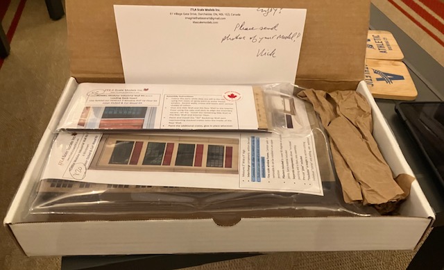
I was ready to start building the bridge from a Central Valley #1902 single-track bridge kit when potential tariffs on products imported from Canada hit the news. Purchasing the ITLA Industrial Wall Modules became a priority. I wanted to fit as much of the structure as possible into the space available, but that was less than 50% of the main building. And this doesn’t include the six large grain silos or the coal dump for the power plant. I chose to model the shorter of the two main sections and forego the other parts of the structure.
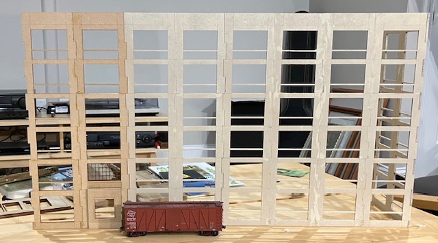
The ITLA product is well engineered and executed. The company’s online videos help with the basics. Several others have posted YouTube videos on their efforts to construct a custom model from these modules; a web search will offer several options. It is worth seeking out others’ experiences.
I am adding these comments as I build the structure. It is a well thought out design, but the amount of time it takes to cut and fit pieces together for a large structure seems unending at times. To make the structure six stories tall it takes multiple precision cuts on vertical sections and then vertical wall sections must be glued and clamped, 22 of them. Then the vertical sections must be precisely glued together flat and true also. And then 66 brick sections have to be painted, weathered, and installed into each section. Near complete?
The “concrete” parts, including the curtain wall structure and pilasters are spray painted with Rust-oleum Camouflage Flat Khaki, lightly over sprayed with Rust-oleum Heirloom White. The separate window frame parts are sprayed a light grey with Rust-oleum Satin Stone Gray. The brick sections are finished with the same Stone Gray, then over sprayed with a Vallejo red and then lightly with a Vallejo orange to represent the brick portions of the wall To highlight the mortar, a wash of thinned Vallejo light grey is brushed on, allowed to slightly dry, and wiped off several times.
Then for my structure, 66 window frames must have the edges sanded and glued into place. Did I mentioned the painting of each piece before adding it to the model? Okay, you get that much repetition is needed. It takes an ongoing effort to build a large model, a piece or two glued and in place every day for a month or two. It takes stamina. I would recommend building the structure in place that you see all the time to keep you working at it. And take and share pictures, it helps you see the progress.
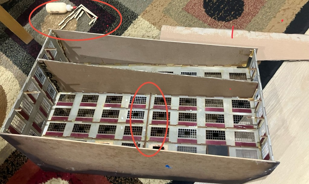
Before adding the base and the roof I used the frets, the strips of wood that hold the laser cut wall sections, to reinforce internal right angle corners and to help keep the building square. The roof and base were cut from 1/8” hardboard. I added floors from foam core to make the interior less empty, painting the floors the dark khaki color.
The roof section is not flat nor sloped, but low slope. It is a distinctive feature of the structure along with the corbels. To replicate the low slope of roof I used 1/8” Masonite for the roof structure. The roof is sprayed with the same colors as the curtain walls to replicate the same concrete color.
One of the finishing touches was adding corbels under the roof overhang. They are constructed from Tichy part #8101 with some Evergreen Styrene #103 and #144 as seen in the photo below. After they were firmly glued in place with thinned Barge cement, I resprayed the upper portions of the structure Rust-oleum Camouflage Flat Khaki, lightly over sprayed with Rust-oleum Heirloom White to blend everything together.
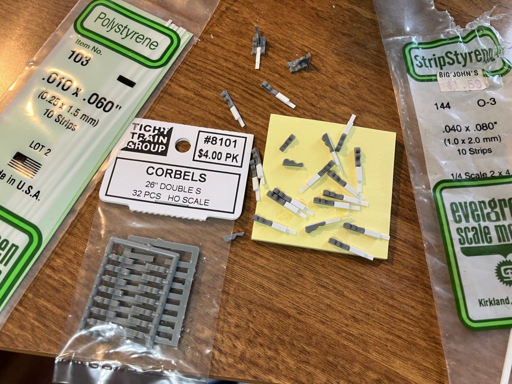
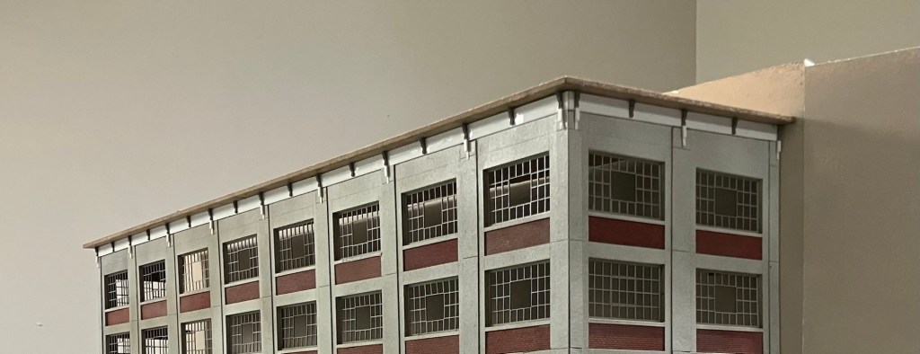
I found a great photograph of the corbels online from the Maryland Center for History and Culture at https://www.mdhistory.org/resources/doughnut-corporation-of-america-factory/ which shows the building just after construction. I found the photo late in the process and some decisions were already made, so my structure misses the mark in a few ways.
An airbrushing with Windsor & Newton Galeria Matte Varnish tinted with Vallejo light grey was applied over the entire structure to blend the colors and add a hint of weathering. The clear plastic for the windows are given a light coat of the clear matte varnish on the interior side to replicate years of dirt, while slightly blurring the view of the interior.
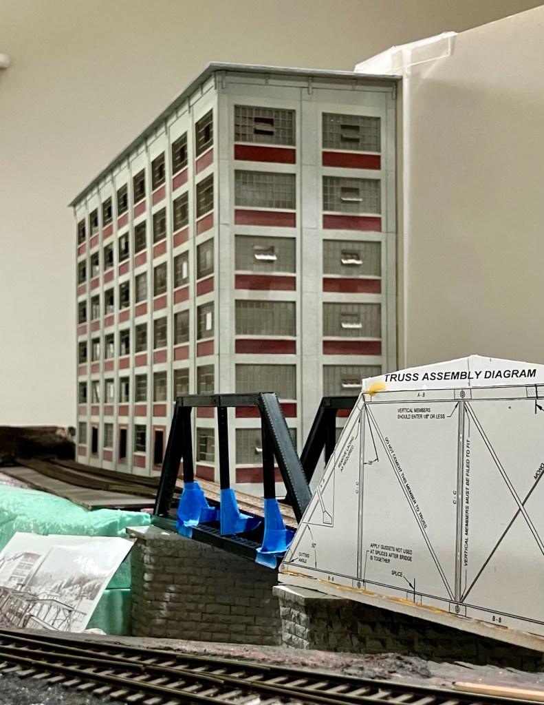
The final installation of scenery, track, and the bridge warrant their own blog posts. They are forthcoming as construction continues.


Good morning Bruce,
Excellent work. Thanks for sharing. I applaud your effort. The ability to pull this out of the hat is very enjoyable for me to see. I can see the hours of research and of your modeling efforts. I lived in Catonsville and to see someone make a model of this structure is very special. Thanks,Barry
LikeLike