For me, model tracklaying is something I am truly afraid to do, afraid to get wrong. I know the consequences of doing it poorly and thus my fear. I have read many articles, watched many videos, and I know if the track isn’t smooth it will forever dampen my modeling experience. For me to be afraid of a physical task is very unusual. I have taken apart automobiles and put them back to together with less concern. I have drilled and tapped an engine block in my only transportation over a weekend and not thought twice. Part of my concern is how soft the parts involved are and the lack of precision. I am used to hard, straight lines, objects that react with precision to precise movements.
I suspect few model railroaders have ever get to lay track on an actual railroad, so I should share that experience. Though I don’t think the two are related. While working on a tie unit (a mechanized workforce that replaces cross ties at a pace of 500 a day) we were diverted one very, very hot day in 1982. I suspect there was fear that our unit would disturb the mainline between Baltimore and Washington so we were diverted. Disturbing the mainline for a Trackman is easy overtime, but for a railroad it is a very bad thing. The disturbance that the B&O was afraid was commonly called a “heat kink” and no one really wanted it. On hot days if the roadbed and ties were moved too much the welded rail would kink. By that I mean a twenty foot or so long section would pop out laterally in one direction or the other. For modelers it is the same expansion we see in our rails, but on a bigger scale. Many times this movement in the rails occurs near bridges but when you move the ties and roadbed, it can happen anywhere. The remedy was overtime, a welding crew to cut out a few feet of rail, a track gang to move the rail back into place (lining bars and a lot of push), hand ballasting and tamping, and then adding joint bars to rejoin the track. The fear of all that overtime probably put my tie unit on this special assignment.

Our task for the day was to add a new siding in the Jessup, MD area. The older Trackman that were machine operators barely got off the bus. While it was a union job no one seemed to care and I was personally happy that some of the old guys laid out in the shade. The switch (turnout) for the siding had been laid and our job was to add a couple of hundred feet of straight siding to reach a warehouse. Sidings are light rail, right? Well a 117 pound rail at a 39 foot section weighs in a little over 1500 pounds. It is not like in the movies, moving it with a four guys with rail dogs. It starts with laying out the ties on a graded roadbed. Ties aren’t too light either, four guys with tie tongs can move a cross tie. Well you get the picture, it was a long day and I am probably better at laying 1:1 track than 1:87 track.
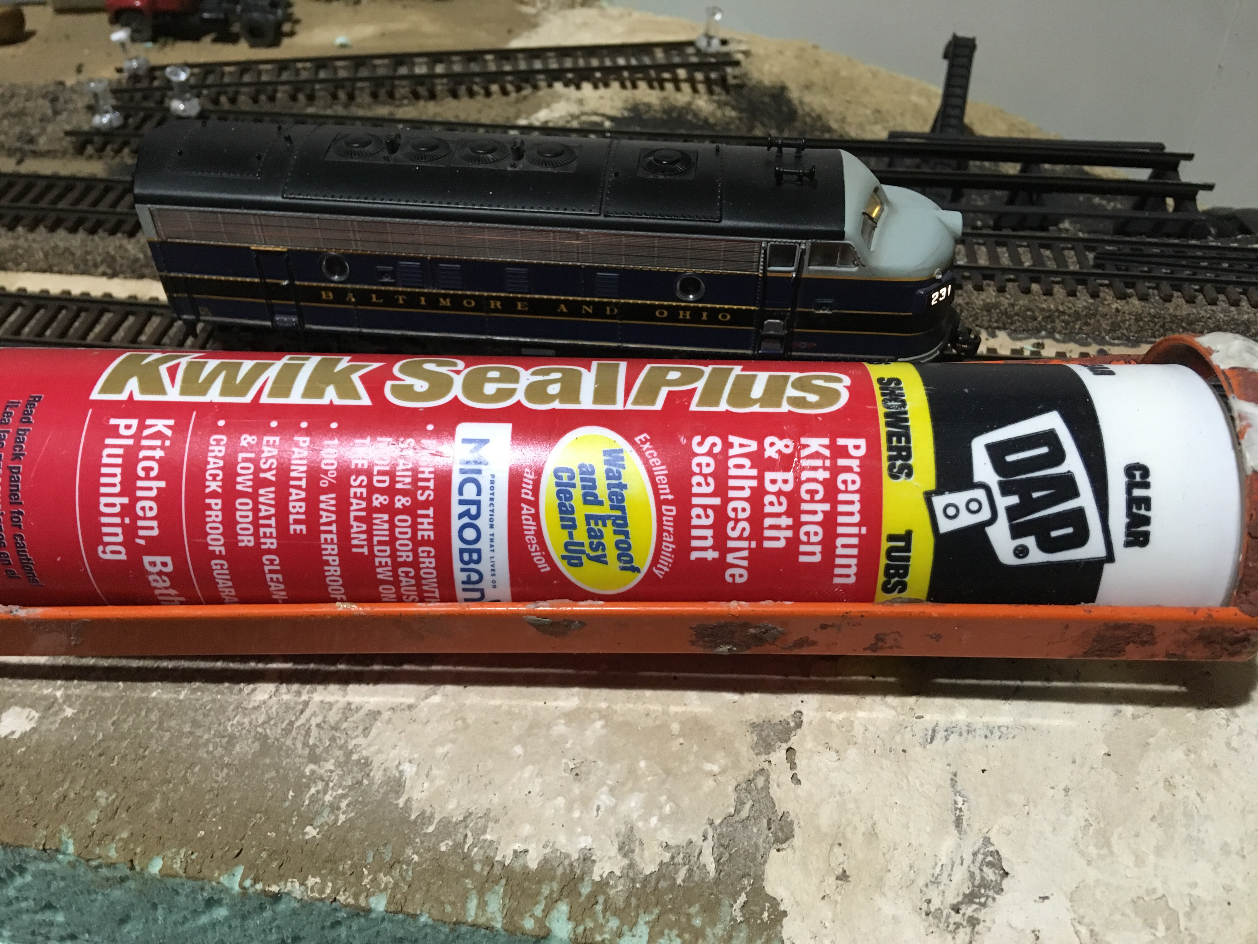
Back to modeling, laying cork roadbed, and flex-track at 1:87 isn’t so precise. Add turnout machines that require relatively precise adjustment, but are attached to plywood with wood screws and thus less precise and it is outside of my comfort zone. My goal is to lay the first four feet of track on the first module, Ilchester, with its bridges, slight curve, and two turnouts. Taking the consensus advice from the Proto-Layout@groups.io, I am going to glue down the cork with adhesive caulk, sand, and then glue the track onto the cork. Some sage advice on deciding on the type of caulk from Tony Koester on the listserve, “Be sure the word ADHESIVE comes between “clear” and “caulk.” And avoid problems by ensuring the letters “DAP” precede the other words.” Got it!

Laying out the track was discussed in a previous blog. I was able to start with black Sharpie line down the middle of each track. The cork was laid along this line with the ends of the cork staggered to help the sections blend. I laid one side at a time by applying a thin layer of adhesive caulk and using thumb tacks every few inches. I used a small tack hammer to make sure the tacks were set down into the plywood subroadbed.
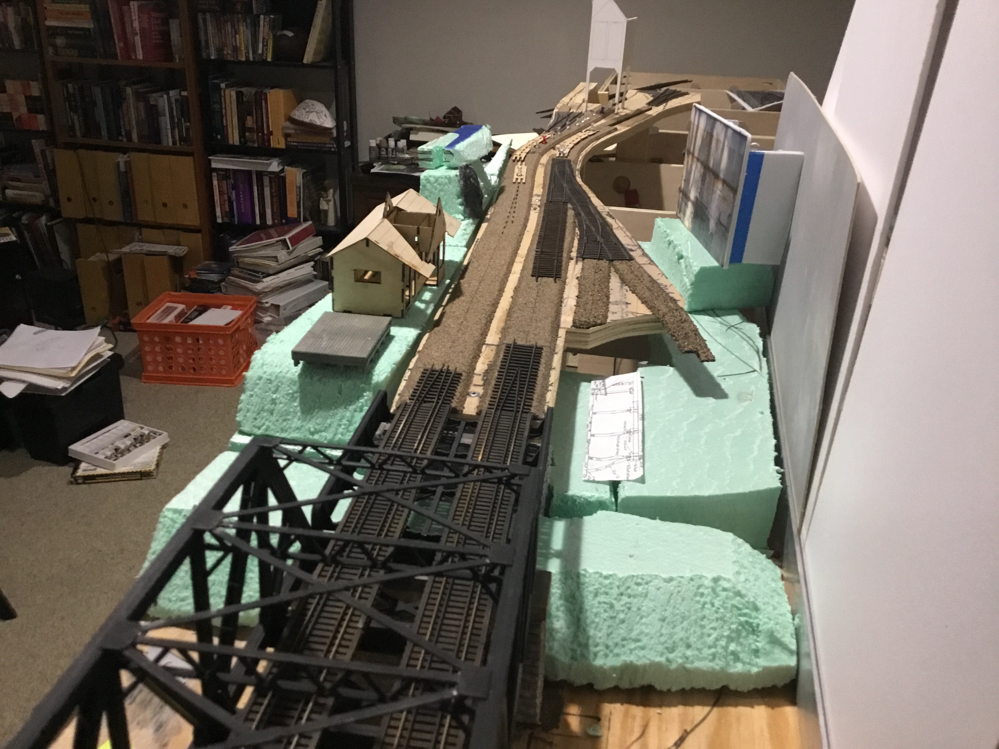
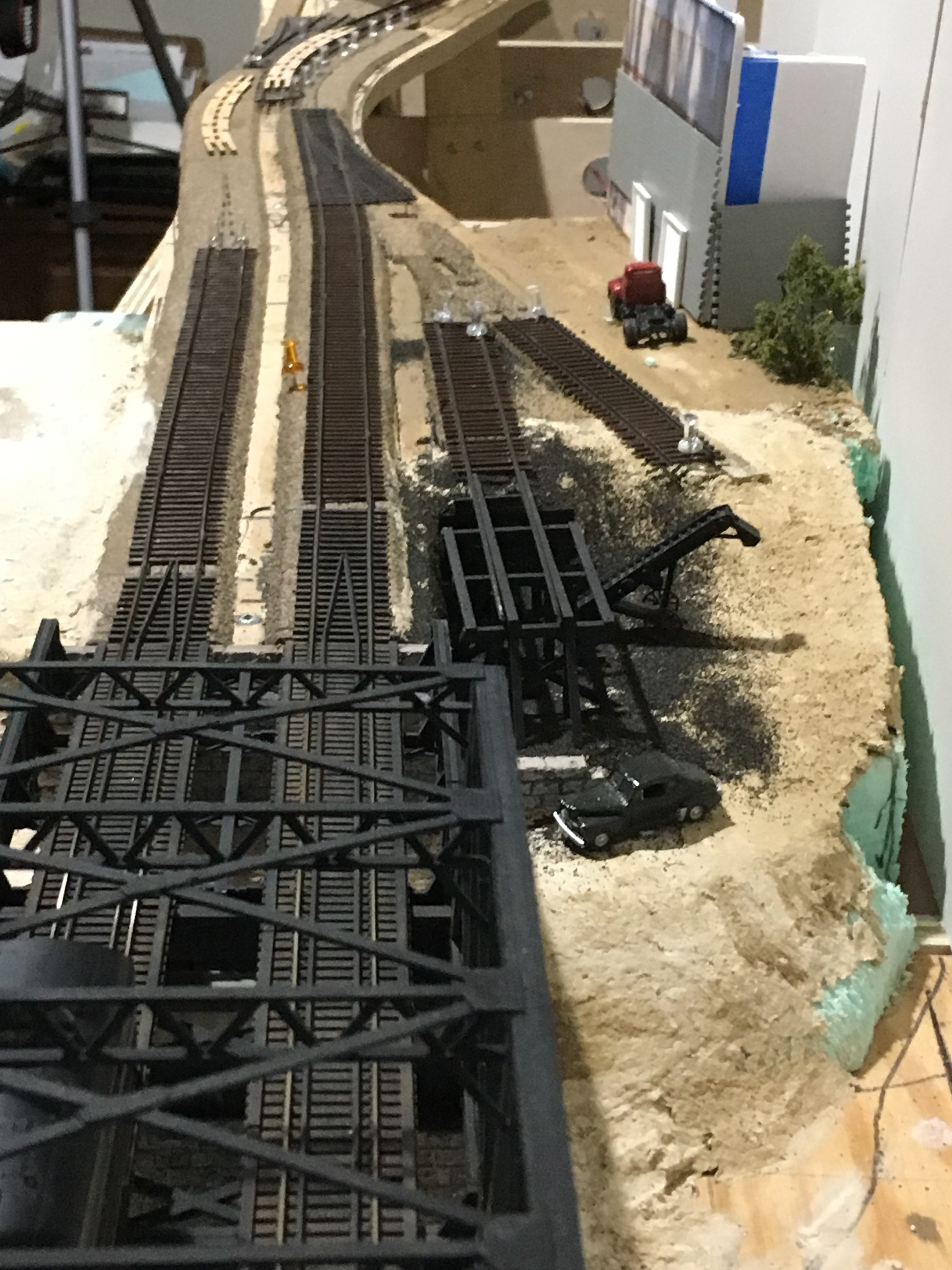
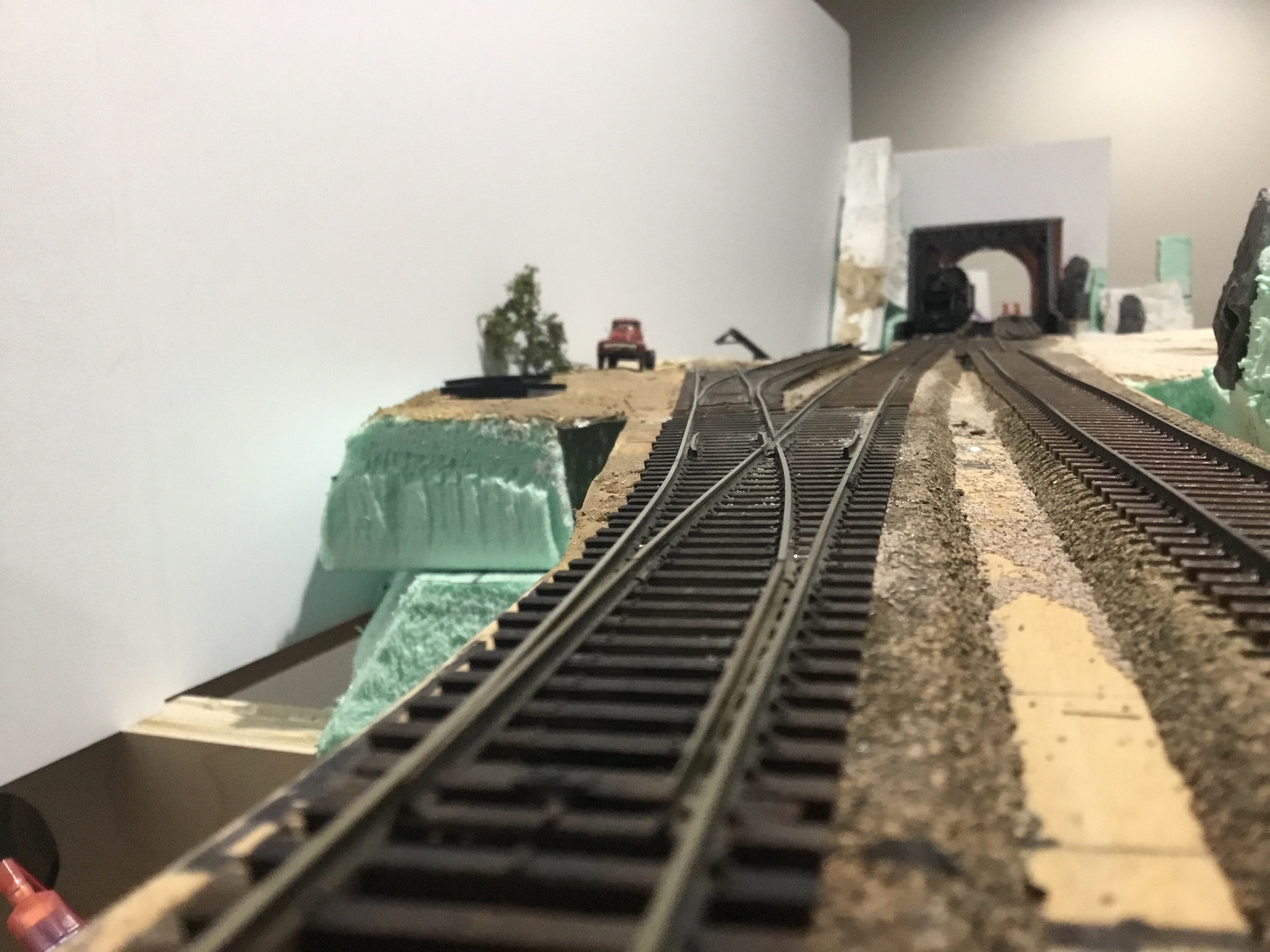
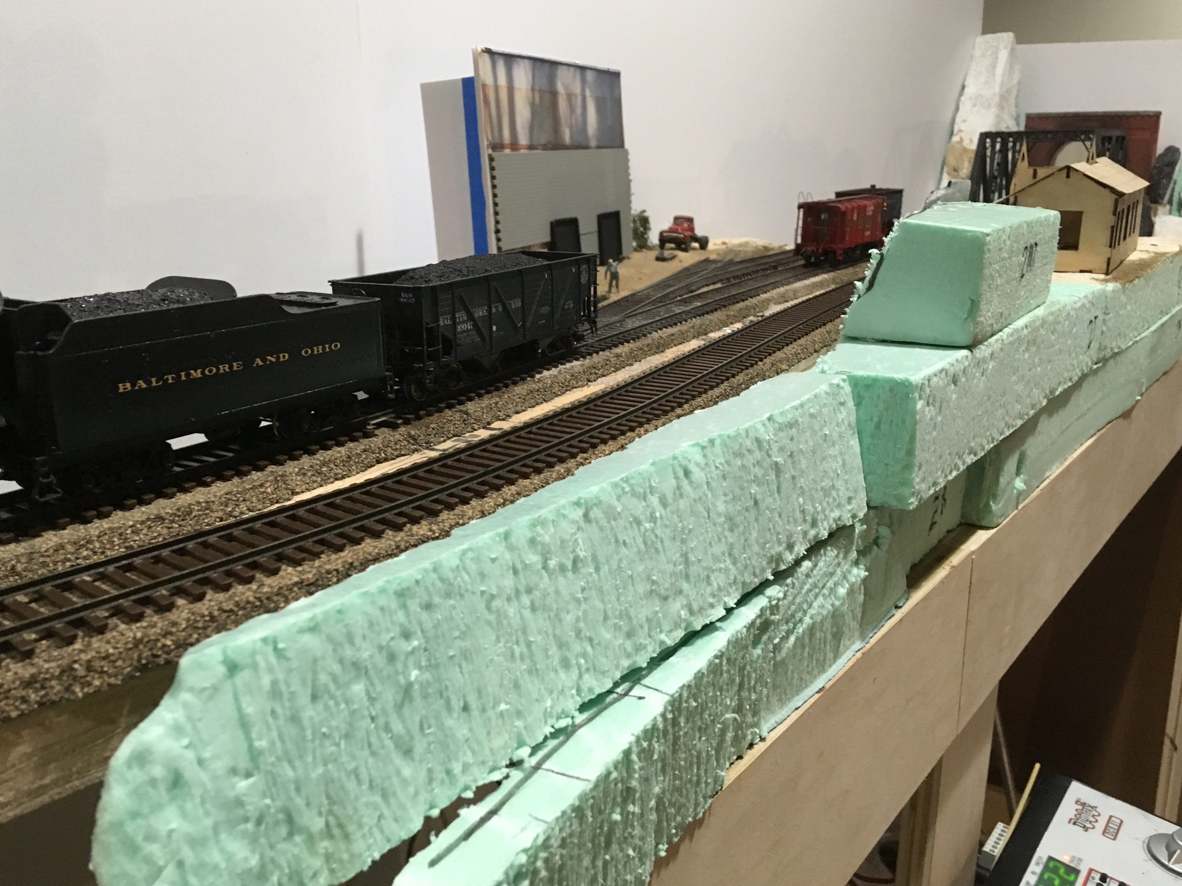
After the caulk adhesive set overnight, I ran a sanding block over the cork to make it as smooth as possible. Well truthfully, I have ran the sanding block over it many times and am trying to lay a turnout that transitions to a siding at a lower rail height with much less ballast. The backdrop in these photos is just some foam core I had lying around to give me a sense of the depth of the scene. It has helped tremendously. It is resting on the aluminum L-girder I intend to anchor Masonite (or maybe Gatorboard) to for the permanent backdrop.

To create the illusion of a significant drop in rail height I am both dropping the rail height slightly and building up the landform around the siding tracks so it appears to be “on the ground.” It is necessary in modeling to shrink length much of the time, thus shorter turnouts, shorter sidings, and less distance to create the prototypical drop in rail height for my siding. With the sanding block I thinned the glued down HO scale cork roadbed and transitioned to N scale roadbed. That along with slightly building up the ground around the siding track will hopefully create the illusion of a greater drop.
At the same time I am added rough cut 2″ insulating foam to create the basic landforms and places for structures. I am not sure how far to go with each process before one interferes too much with the other. This experimentation is the advantage of working on one module at a time. Or so I hope, maybe I should have started with a simpler module. In the photo below, the mock-up structure to the right is the Bartgis Brothers power plant and the basic structure of the MJB Models Ilchester Station kit is to the left. The Lees Coaling Tower mock-up in the distance in the center. Exciting blogs to follow for each.
Time to cut some full length pieces of flex track sections to use as few pieces as possible between the bridge and the turnouts on each track. This required some shaping of the track detailed later. Each rail gets its own feeder wire, I am using red wire for the south rails and black for the north. I’ve seem it done two ways, one soldered to the web on the side away from typical viewing underneath the base of the rail. Both methods have proponents and I chose to solder to the bottom of the rail. I am not bad at soldering but this allows for some error and keeps the hot iron away from the visible plastic tie surface and the relatively small spike detail on the ME track that keeps it together. I actually used a light touch with Dremel tool with a wheel to scare the bottom of the rail and create a clean surface. I am using a Weller WLC100 40 Watt Soldering Station on its high setting with a Weller ST7 Conical Solder Tip, 0.31″. The idea is high heat in a small space to melt the solder quickly and get it back away from the plastic ties. The ground and dressed rail bottom is flushed with some liquid electronic soldering flux and tinned (adding a thin layer of solder to the surface). The a tinned feeder wire bent in an “L” shape get a touch of flux and is touched to the rail with the hot iron and held until cool. There are plenty of videos online to assist in this technique, but watch several and learn from them all to get a consensus of what works. No one knows everything and by watching them all you can pick up tips from each and develop your own “best practice” for soldering rail. I am relying on these feeders to the bus wire for power to the rail, so I am not soldering the physical rail joints. Only final word at this stage. Test every soldered connection for continuity with a multi-meter, it will payoff later if there is a problem.

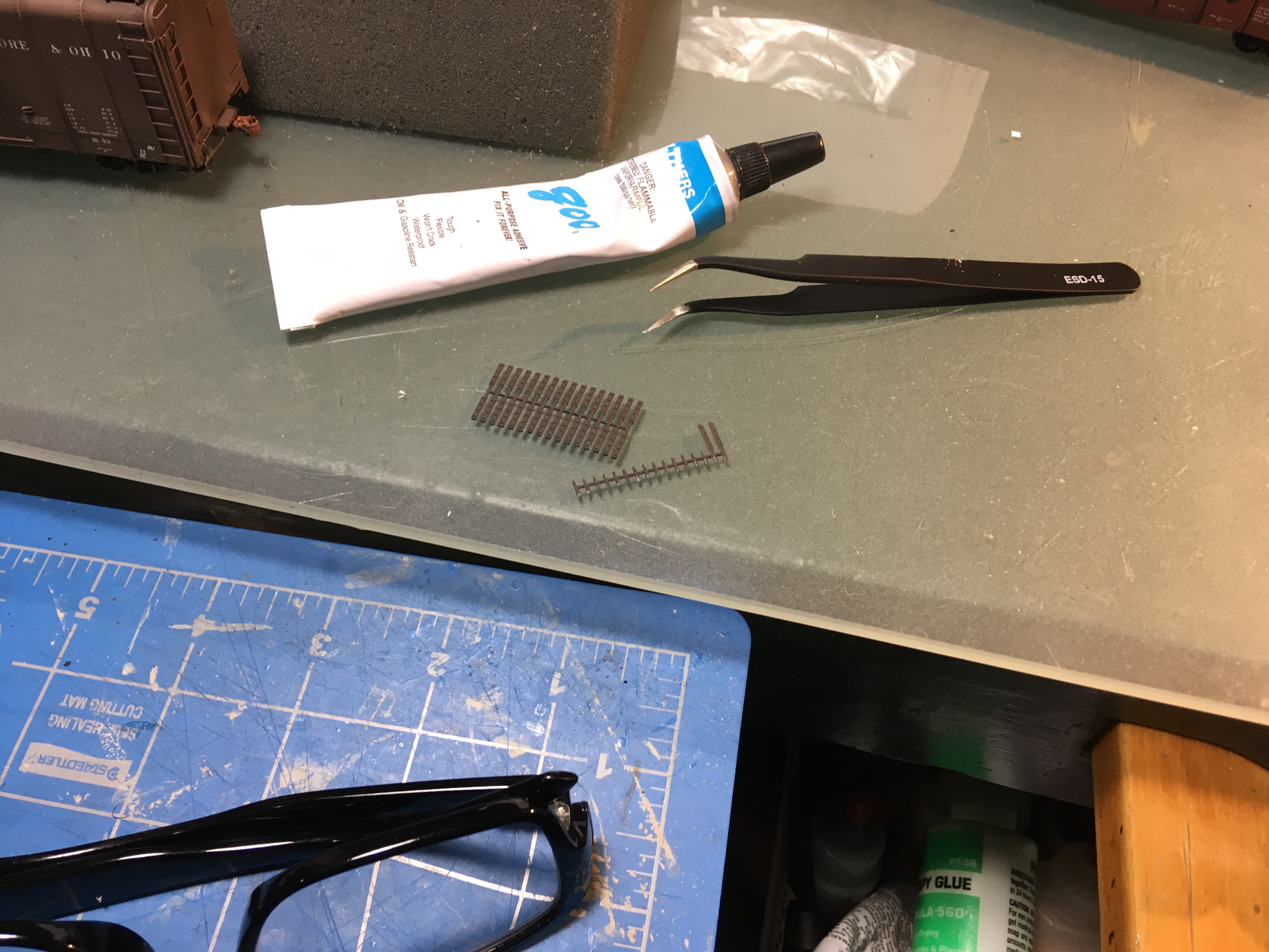
For some additional detail, I decided add “scale” joint bars from HE6AGON that I found on Shapeways. They are called ME83 Joint Bars, Four Bolts. https://www.shapeways.com/product/UYEUNPE25/me83-joint-bars-four-bolts I added them at 39′ intervals with CA. I used an Atlas Super Track Saw to cut joints about 1/4 of the way through the top of the rail. I am not sure CA was the right choice as the dissimilar materials will expand and contract differently and may cause the glue joint to fail. Future scale joint bars will be added with more flexible Pliobond and GOO adhesive. The installed joint bars do tend to disappear when viewed from the side. They are a more apparent looking down the track longitudinally and therefore with the effort to me. I consider it like underbody brake detail on a freight car, it is only partially visible but enjoyable and worth the time spent.
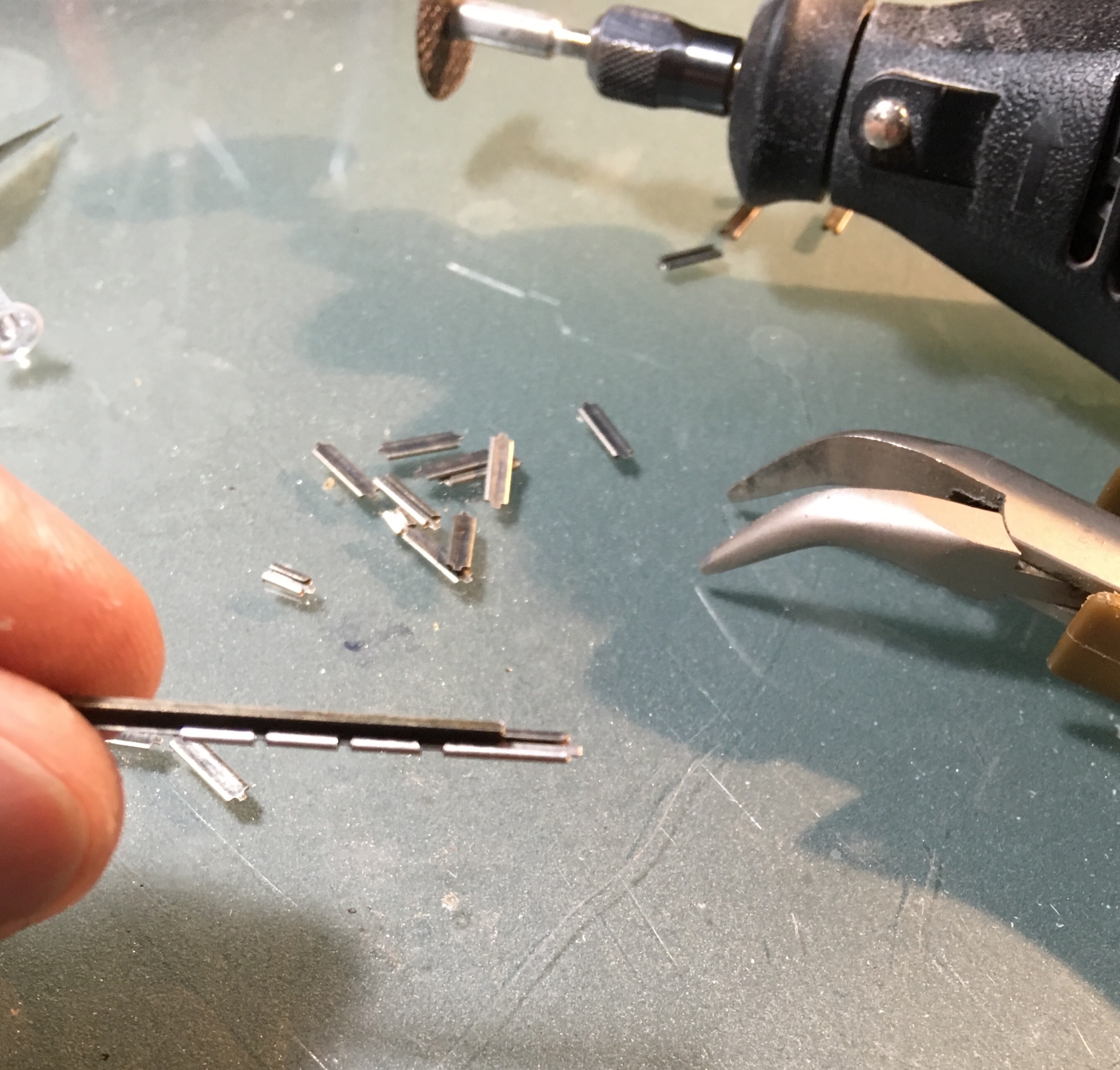
The joiners that physically hold sections of flex track and turnouts together are Micro Engineering HO 26-083 Code 83 Nickel Silver Rail Joiners that have been cut in half to help hide them in the ballast. To cut them I took a short length of scrap rail, slid on a rail joiner and cut it in “half” with a Dremel cutoff wheel. Afterwards, I slide the cut joiner down the rail to open up the end that was cut (see photo). The result is one half-length joiner, the other side is too short so each full rail joiner yields only one because of the cutoff wheel width. Not a big sacrifice, they are cheap and this process is quick. A touch of rail brown paint and they disappear and about half will get trimmed scale joint bars above them for further camouflage.
When laying the track, I first laid it in place and bent it into shape. Some dislike ME track because it tends to hold its shape when bent. I use the Fast-Track Sweepsticks straight and curved pieces I used in planning (see previous blog on Layout) to set the track to the shape I want and take advantage of this feature. Final trimming to length is done at this point. On occasion, I have added a drop of CA to the tie plate/rail joint to keep the shape if it starts to flex back to straight. With everything where I want it and rail joiners in place, I run my most finicky steam locomotive over the line multiple times.
By doing this I discovered an actual “low joint”. I must have bent the rail slightly on the vertical axis while cutting the joint bar locations. This may be a wanted effect on a well worn branch in the 60s but not welcome on my mainline. A track gang was dispatched to dig out the ties, add some stone, tamp up, and respike the ties. That only works on the real thing, for my model I used a some gentle hand pressure to straighten the rail. Maybe in another blog I will describe how a track gang fixes a low joint with a tamping fork, it’s a two man operation.
The shortened rail joiners actually provide decent electrical continuity between rail sections, as terminating the rail feeder ends to the bus wire is my last step. To make life a little easier for the first module, I purchased the NCE Layout Wiring Kit, NCE 5240268. It includes enough red and black bus wire for my layout, several short rail drops, termination spade clips, and suitcase connectors that connect to the bus to spade terminations. The hope was to make the whole wiring process go a little smoother. It’s a beginner kit and maybe a little expensive, but I’m a beginner, and I am hoping this reduces the likelihood of an electrical fault. As stated at the beginning of this blog, this exercise is outside my comfort zone and I realize it is very important if I am to enjoy my layout for a long time.
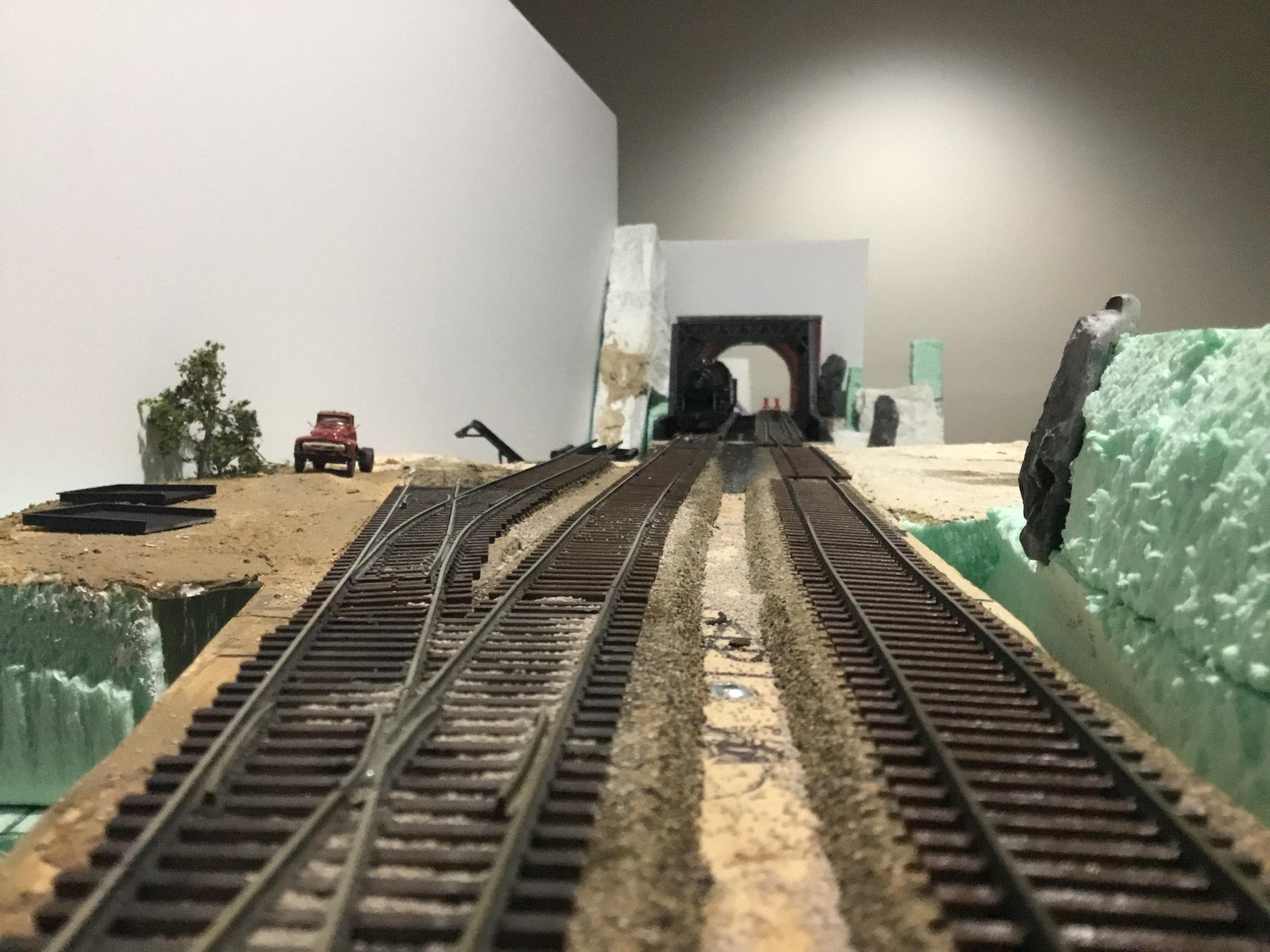
Final sighting of the track to make sure it is straight where it is supposed to be and the curves transition smoothly is a visual exercise. I am fortunate with this section to be able to view the track longitudinally and spot minor kinks that are not apparent from the side view. One trick that worked for me was to add a thumb tack to give me a reference point as to where the kink is located. A bit of back and forth and the pin is located at the kink and then the track is aligned to match the overall profile. It is a depth perception aid. It is a hand exercise after the scale joint bars are added as the Fast Tracks Sweepsticks don’t fit into the track due to interference from the bars. Not a problem at this point, everything is pretty close to the design.
Gluing the track in place is the moment of truth, so I am doing it first thing in the evening when I get home and am fresh. All the prep work really paid off as I was able lift the rail out of the way with the feeder wires still through the roadbed and add a thin bead of adhesive caulk. Flattening the bead with a plastic putty knife leaves me with a thin layer of adhesive caulk. I tried to get a consistently thin layer so it would not squeeze up between the ties, just enough to make contact. Again, prep work pays, the sanding and sighting kept me from last minute emergencies with wet adhesive in place.
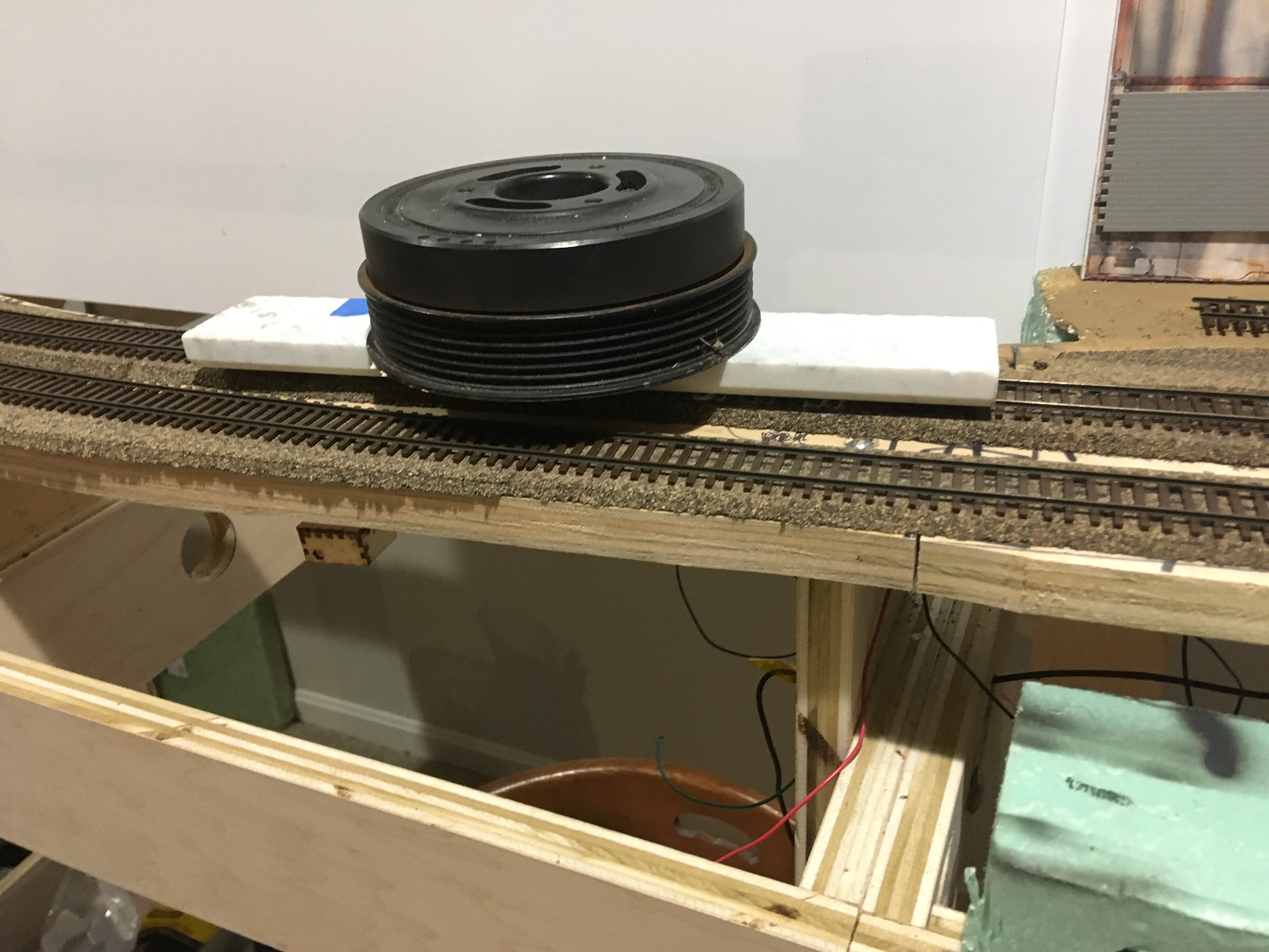
I used several methods to hold the track in place while the adhesive set depending on the situation. One method was thumb tacks tapped lightly into place over the rail head, making sure to put some pressure on the track but not enough to bend the rail or distort the ties. For flat, level sections I use some marble floor tile transition pieces from a home improvement project. Cheap, flat, and they have some mass. They also make nice display bases for models if you use the narrow ones. When I needed a more dense weight I used the old crankshaft dampener/pulley from my Mini Cooper S (I said I don’t mind pulling apart a car and the used parts have other uses).
I held my iPad on the rail and snapped a few pictures before adding the tacks and weight to be sure things looked smooth from track level. An easy way to get a track foreman’s view of the work. A day later I was happy with my results. I only did one section a day and left the turnouts for later (and a later blog). Connect the track feeder drops to the bus wires and I’m ready to test the track gang’s work.
One final operational check is to test the continuity of every wire and joint. It only takes minutes but should make it easier to find future issues if I know I started with everything working as planned. It’s a good baseline and if a change in performance occurs after a future modification, you can be a little more certain that the recent modification caused the glitch and it wasn’t from previous work. With all power off and the DCC power unit disconnected from the bus wire I connect one lead of my multi-meter to one side of the bus and then test each piece of rail that is supposed to be connected to that side. I did find two loose spade to suitcase connections, but my solder joints remained solid and everything is now connected to the main bus wires. Reconnect the bus line to the DCC power unit and run some trains, again checking for low or high spots, bad joints, etc.

The next step will be ballasting the mainline and popular wisdom suggests this be a later step after more scenery and ground cover are in place. Anyway, this blog is long enough, I will add some more as I add further detail and ballast. Next track work issue is the turnouts. Thanks for following along.

Looking good! I really like your comments on using Pliobond/Goo vs CA adhesive for the tie plates. I am scratch building some curved turnouts and am following along with some of the FastTracks wisdom/method; they use Pliobond for attaching ties to the bottom of the rails. I will probably pick up a tube. I’m worried about it drying in the tube in between jobs. I really like the joint bars you linked. I’ve been using Walthers/Shinohara C83 for the “main line” on my own layout; I wonder if these joint bars will work on that type of track. Using the Atlas track saw to cut “joints” in the rails – is the notch too wide? How does it look?
LikeLike
Thank you. I really like Pliobond as it is more liquid than Goo. My tube is good after a year and I use the tip offered by Fast Tracks. After each use, I clean out the tip with alcohol and a toothpick. Check the link for the joint bars, I think they offer product for different track manufacturers. The saw cut is more narrow than a Dremel cut and I cut only through the head of the rail. It is subtle.
LikeLike